Mechanical engineering part cleaning and machining equipment

A technology of mechanical engineering and processing equipment, applied in lighting and heating equipment, dryers, cleaning methods and utensils, etc., can solve problems such as inability to clean, affect the later use of products, and incomplete cleaning, so as to improve the cleaning effect and improve the The effect of the tilt effect

Pending Publication Date: 2021-02-05
WEST ANHUI UNIV
View PDF6 Cites 6 Cited by
  • Summary
  • Abstract
  • Description
  • Claims
  • Application Information

AI Technical Summary

Problems solved by technology

[0003] However, the existing parts cleaning device often simply washes or blows the mechanical parts, and cannot realize sufficient contact between the cleaning liquid and the parts, and at the same time cannot clean each part on the parts, and the cleaning is not thorough. To a certain extent, it affects the later use of the product

Method used


Image

  • Mechanical engineering part cleaning and machining equipment
  • Mechanical engineering part cleaning and machining equipment
  • Mechanical engineering part cleaning and machining equipment

Examples


Embodiment 1

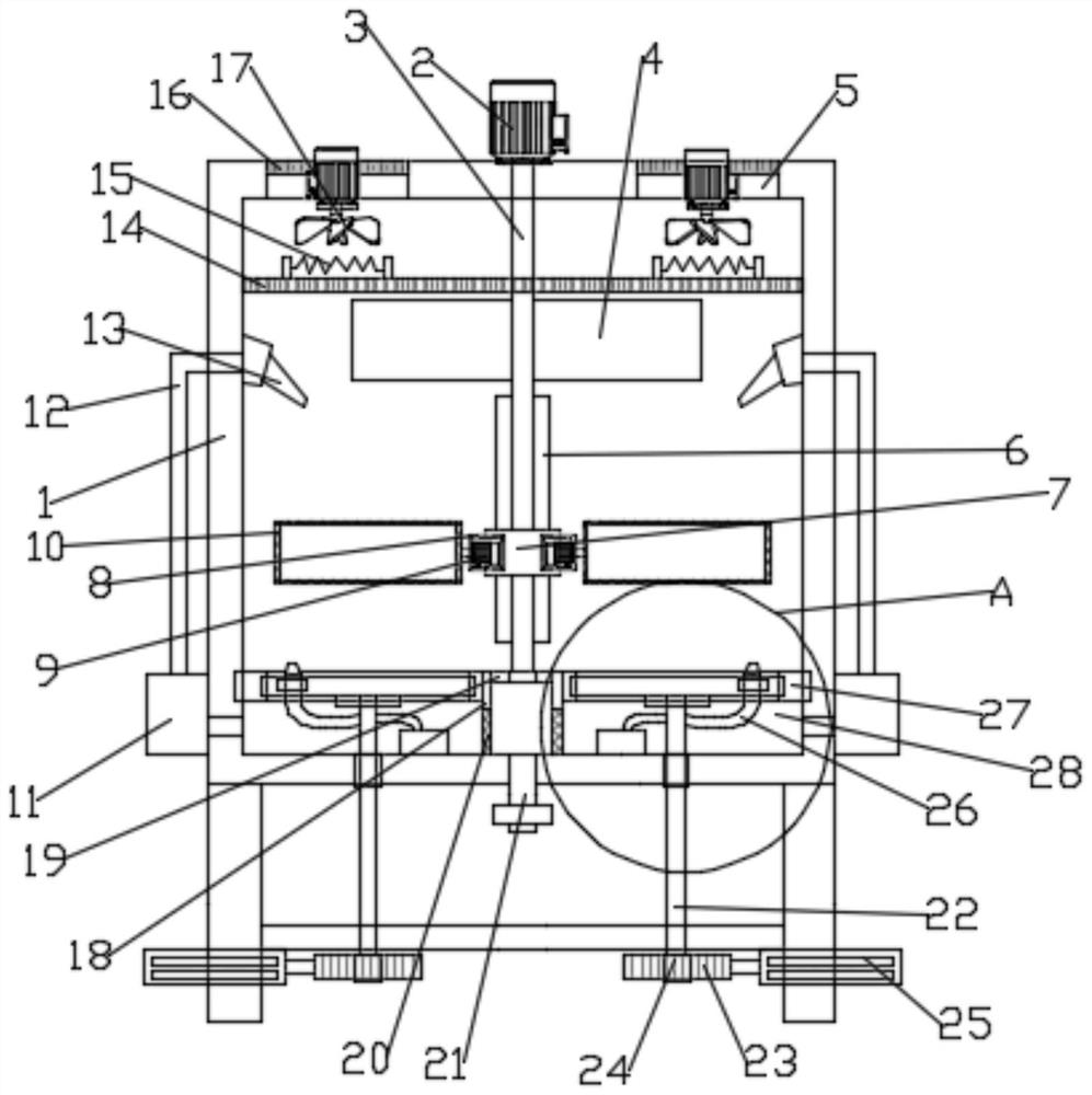
[0024] Such as figure 1 As shown, in the embodiment provided by the present invention, a mechanical engineering parts cleaning and processing equipment includes a box body 1, and an adjusting screw 3 is rotatably arranged in the inner cavity of the box body 1, and the box body 1 A positive and negative servo motor 2 for driving the adjustment screw 3 to rotate is installed on the top plate; the lifting screw sleeve 7 that is slid up and down in the inner cavity of the box body 1 is sleeved on the adjustment screw by threaded connection 3, therefore, according to the rotation direction of the screw rod 3 driven by the forward and reverse servo motor 2, the height position of the lifting nut 7 can be adjusted;

[0025] Further, such as figure 1 and Figure 4 As shown, in the embodiment provided by the present invention, a motor box 8 is fixedly installed on both sides of the lifting screw sleeve 7, and a drive motor 9 is fixedly installed in the motor box 8, and the output sha...

Embodiment 2

[0030] Such as figure 1 As shown, in the embodiment provided by the present invention, a mechanical engineering parts cleaning and processing equipment includes a box body 1, and an adjusting screw 3 is rotatably arranged in the inner cavity of the box body 1, and the box body 1 A positive and negative servo motor 2 for driving the adjustment screw 3 to rotate is installed on the top plate; the lifting screw sleeve 7 that is slid up and down in the inner cavity of the box body 1 is sleeved on the adjustment screw by threaded connection 3, therefore, according to the rotation direction of the screw rod 3 driven by the forward and reverse servo motor 2, the height position of the lifting nut 7 can be adjusted;

[0031] Further, such as figure 1 and Figure 4 As shown, in the embodiment provided by the present invention, a motor box 8 is fixedly installed on both sides of the lifting screw sleeve 7, and a drive motor 9 is fixedly installed in the motor box 8, and the output sha...


PUM


Abstract

The embodiment of the invention relates to the technical field of mechanical engineering, and particularly discloses mechanical engineering part cleaning and machining equipment. The equipment comprises a box body. According to the embodiment of the invention, the height position of a lifting screw sleeve can be adjusted according to the rotating direction of an adjusting screw rod driven by a positive and negative rotation servo motor; by starting a liquid pump and a booster pump, cleaning liquid in an inner cavity of the box body can be disturbed through a second nozzle, and the inclinationeffect on mechanical parts in a storage net box is improved; by means of the extension function of an electric extensible rod, a toothed plate is pushed to move, then a rotating shaft is driven to rotate under the linkage effect of the toothed plate and a gear which are meshed with each other, then a rotating disc is driven to rotate, the range of liquid flow sprayed out of the second nozzle is wider, and the cleaning effect on the mechanical parts in the storage net box is improved; and air flow can be introduced into the box body by starting an air blower, and the air flow is heated by a electric heating net and is then blown to the storage net box, so that the mechanical parts in the storage net box are dried.

Description

technical field [0001] The embodiment of the invention relates to the technical field of mechanical engineering, in particular to a cleaning and processing equipment for mechanical engineering parts. Background technique [0002] There are all kinds of mechanical parts in the field of mechanical engineering. Mechanical parts, also known as mechanical components, are the basic components of machinery, and they are inseparable individual parts that make up machinery and machines. Mechanical parts will inevitably produce oil stains and dirt during long-term work, so they need to be cleaned. [0003] However, the existing parts cleaning device often simply washes or blows the mechanical parts, and cannot realize sufficient contact between the cleaning liquid and the parts, and at the same time cannot clean each part on the parts, and the cleaning is not thorough. To a certain extent, it affects the later use of the product. Contents of the invention [0004] The purpose of t...

Claims


Application Information

Patent Timeline
Patent Type & Authority Applications(China)
IPC IPC(8): B08B3/02B08B3/04B08B13/00F26B11/18F26B21/00B01D29/03
CPCB01D29/03B08B3/02B08B3/04B08B13/00F26B11/18F26B21/001F26B21/004
Inventor 王洪新张鹏程振邦
Owner WEST ANHUI UNIV
Why Eureka
Try Eureka