
Bubbling rinsing mechanism with rotating function

A technology with bubbling rinsing and rotating functions, applied in the field of mask cleaning, can solve problems such as dead corners, inability to effectively remove foreign objects in workpieces, etc., to save costs, avoid insufficient cleaning, and improve cleaning effects.

Active Publication Date: 2019-12-17
成都拓维高科光电科技有限公司
View PDF12 Cites 0 Cited by
  • Summary
  • Abstract
  • Description
  • Claims
  • Application Information

AI Technical Summary

Problems solved by technology

At present, the existing rinsing tank is laid with a gas pipe with a well-shaped structure, and a number of air holes are opened on the upper surface of the air pipe, and the gas is transported into the air pipe through an electric air pump, and the gas is discharged from the air holes to form bubbling, but there are rinsing tanks with this structure. The dead angle area makes it impossible to effectively remove foreign matter on the surface of the workpiece when rinsing the workpiece

Method used


Image

  • Bubbling rinsing mechanism with rotating function
  • Bubbling rinsing mechanism with rotating function
  • Bubbling rinsing mechanism with rotating function

Examples


Embodiment 1

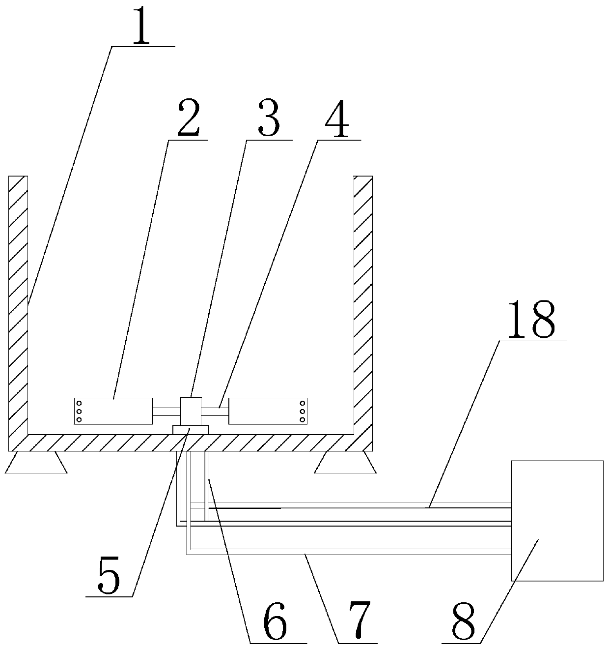
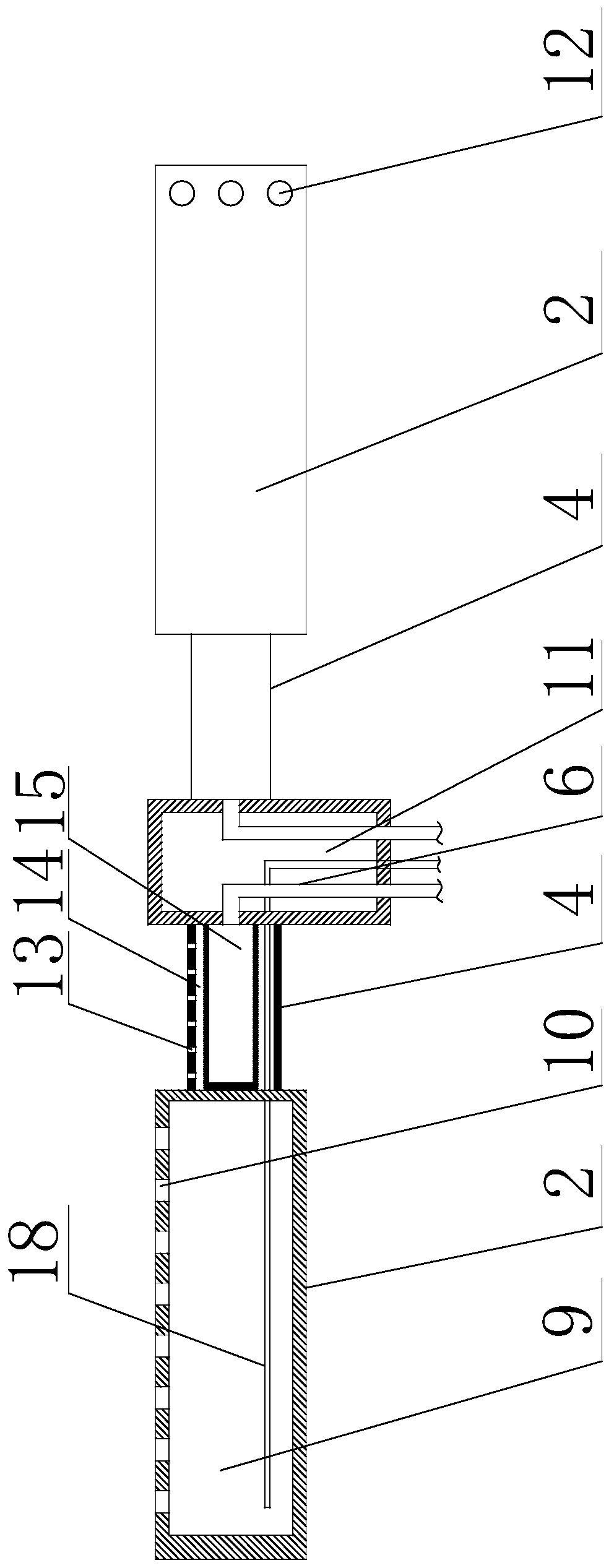
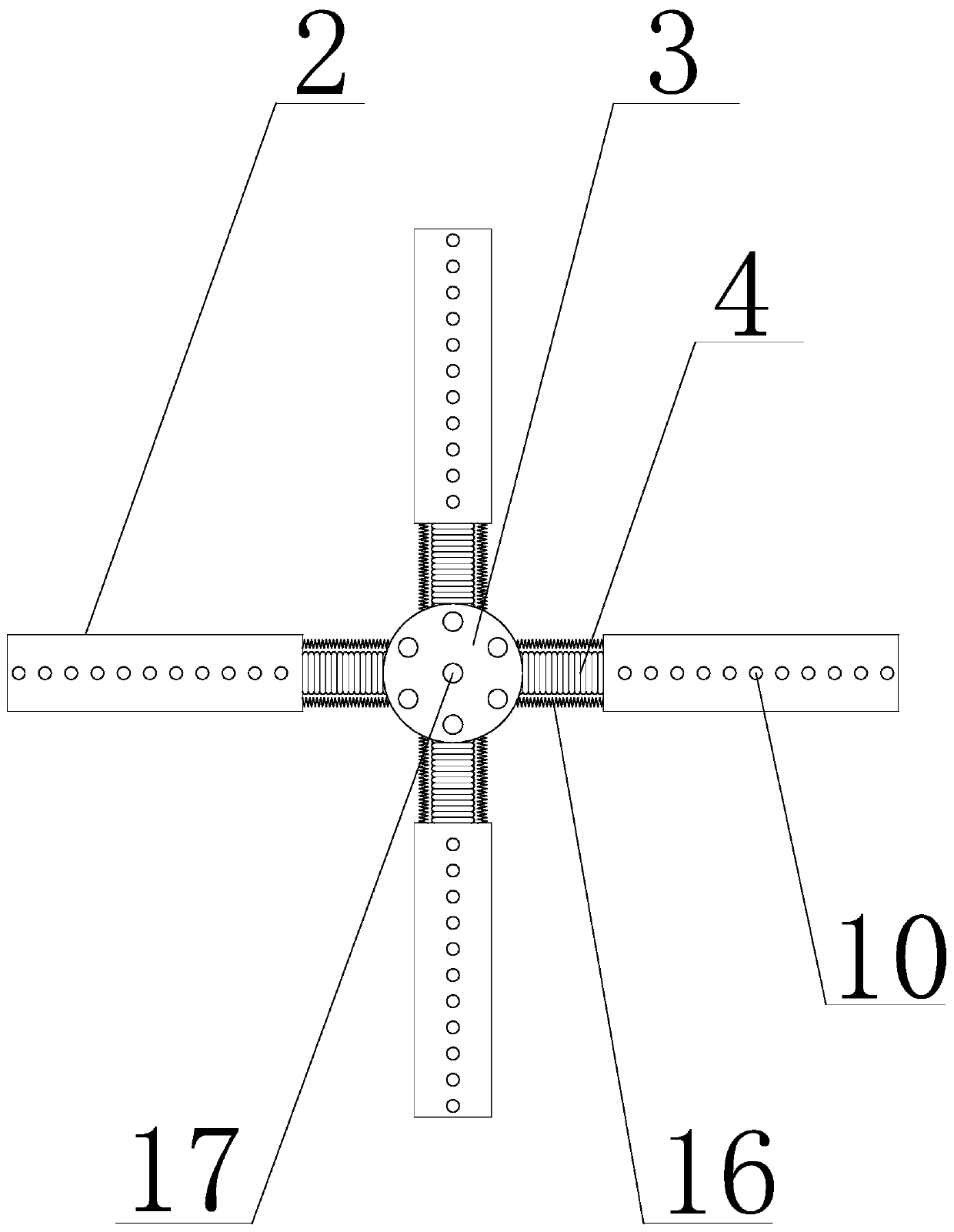
[0033] Such as figure 1 As shown in 4, a bubbling rinsing mechanism with a rotating function in the present invention includes a pool body 1 and an electric air pump 8. The inner bottom of the pool body 1 is provided with a movable rod 3, which can rotate around its axis Rotate in the opposite direction, the outer peripheral wall of the movable rod 3 is provided with several bellows 4, the length of the bellows 4 can be stretched after the interior of the bellows 4 is inflated, one end of the bellows 4 is connected with the inner wall cavity 11 of the movable rod 3, and the other end is connected to the inner wall cavity 11 of the movable rod 3. Stirring plates 2 are all provided, and the upper surface of the stirring plate 2 is provided with some vertical nozzles 10, and the vertical nozzles 10 are evenly distributed along the long axis direction of the stirring plate 2, and some horizontal nozzles are arranged on both sides of the stirring plate 2. Nozzle 12, the first air v...

Embodiment 2

[0035]On the basis of Embodiment 1, the bellows 4 is provided with a cavity 15, and the cavity 11 of the movable rod 3 is also provided with the same number of first air pipes 6 as the bellows 4, the first air pipes One end of 6 is connected to the output end of the electric air pump 8, and the other end is communicated with the cavity 15. The bellows 4 is also provided with an annular cavity 14, the annular cavity 14 communicates with the cavity 11 of the movable rod 3, and the top of the bellows 4 is also provided with a plurality of first air holes 13, and the first air holes are along the corrugated surface. The axial direction of the pipe 4 is distributed, and the first air hole 13 communicates with the annular cavity 14 .

Embodiment 3

[0037] On the basis of Embodiment 2, the stirring plate 2 is provided with an air collecting chamber 9, the air collecting chamber 9 communicates with the annular cavity 14, the vertical nozzle 10 communicates with the air collecting chamber 9, and the air collecting chamber 9 is provided with There is a third air delivery pipe 18, one end of the third air delivery pipe 18 communicates with the horizontal nozzle 12, and the other end passes through the annular cavity 14, and the cavity 11 is connected with the output end of the electric air pump 8 in turn.


PUM


Abstract

The invention discloses a bubbling rinsing mechanism with a rotating function. The bubbling rinsing mechanism comprises a pool body and an electric air pump. A movable rod is arranged on the inner bottom of the pool body; a plurality of corrugated pipes are arranged on the peripheral outer wall of the movable rod; one end of each corrugated pipe is communicated with an inner wall cavity of the movable rod, and the other end of each corrugated pipe is provided with a stirring plate; a plurality of vertical nozzles are arranged on the upper surface of each stirring plate, and the vertical nozzles are uniformly distributed in the long axis direction of the stirring plate; a plurality of horizontal nozzles are arranged at the two sides of the stirring plate; each horizontal nozzle is internally provided with a first air valve; the horizontal nozzles are close to the tail end of the corresponding stirring plate; the output end of the electric air pump is provided with a second air conveyingpipe; the second air conveying pipe communicates with the cavity of the movable rod; and the air in the cavity can be exhausted through the vertical nozzles and the horizontal nozzles. When a mask plate in the pool body is rinsed, the air generated by the electric air pump can drive the stirring plates to rotate, so that it is guaranteed that bubbles can be generated in the pool body, and the cleaning effect on the mask plate is improved.

Description

technical field [0001] The invention relates to the technical field of mask plate cleaning, in particular to a bubbling rinsing mechanism with a rotating function. Background technique [0002] With the development of the semiconductor manufacturing process, the area of ​​the semiconductor chip is getting smaller and smaller, so the precision of the semiconductor process becomes more important. In the semiconductor manufacturing process, one of the important processes is photolithography, which is a process of transferring the pattern on the mask plate to the photolithographic pattern on the semiconductor. The mask plate used in mask exposure is usually coated with a layer of chromium on the quartz glass, and the required pattern is produced through the exposure etching process. The exposure experiment cannot be carried out after the mask plate is dirty, otherwise the dirty mark on it It will be transferred to the photoresist without reservation, therefore, the cleaning of ...

Claims


Application Information

Patent Timeline
Patent Type & Authority Applications(China)
IPC IPC(8): G03F1/82B08B3/10
CPCG03F1/82B08B3/102B08B3/10
Inventor 王照忠王宏宇蒋小华
Owner 成都拓维高科光电科技有限公司
Learn More