Automatic mechanical part machining clamp

A technology of mechanical parts and fixtures, which is applied in the field of automatic mechanical parts processing fixtures, and can solve the problems of low clamping and clamping of processed parts

Pending Publication Date: 2021-02-05
LINYI YINXIN ENG MACHINERY CO LTD
View PDF0 Cites 2 Cited by
  • Summary
  • Abstract
  • Description
  • Claims
  • Application Information

AI Technical Summary

Problems solved by technology

[0002] In the process of component processing of CNC machine tools, it is necessary to fix the components processed in the assembly line to facilitate the subsequent spraying or soaking process of the components, but usually the clamps used to clamp the components can only clamp the outside of the processed components , and for the groove part on the part or the part with irregular shape, the common fixture cannot extend into the groove to clamp the groove part, and the clamping degree of the processed part is low

Method used


Image

  • Automatic mechanical part machining clamp
  • Automatic mechanical part machining clamp
  • Automatic mechanical part machining clamp

Examples


Embodiment Construction

[0028] The following content describes the specific implementation manner of the present invention in detail in conjunction with the accompanying drawings.

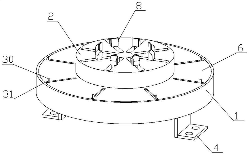
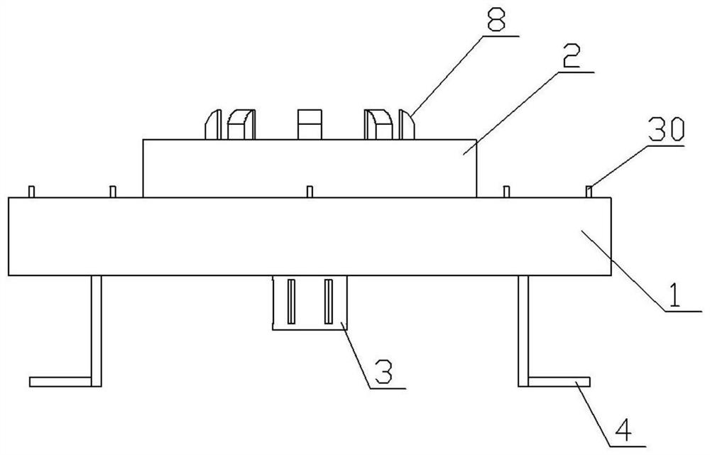
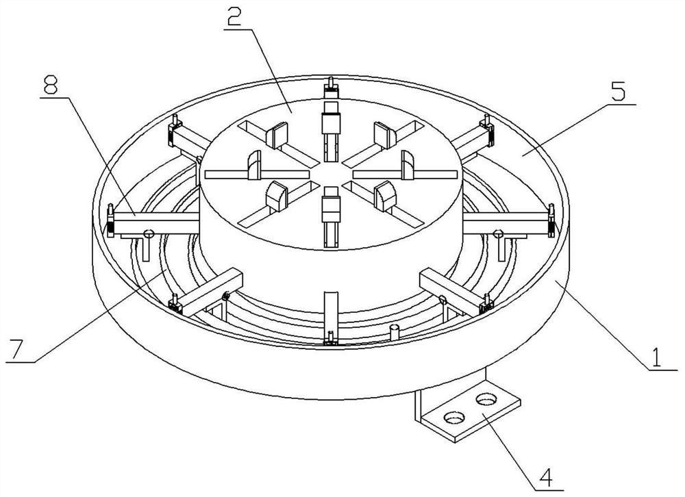
[0029] A jig for processing automatic mechanical parts, including a jig body 1, a guide plate 2 for guiding the clamping direction, and a motor 3. A motor 3 is arranged on the lower side of the jig body 1, and the driving end of the motor 3 extends through the jig body 1 to the void. The cavity 5 is connected to one end of the spiral center of the mainspring 7. The driving end of the motor 3 drives the mainspring 7 to shrink inwardly and extend outwardly for reset. There is a cavity 5, the upper side of the cavity 5 is provided with a pinch plate 6, and several rod grooves 31 are set on the pinch plate 6, and a spring 7 and multiple sets of clamping bodies for clamping the processing parts are provided in the cavity 5 8. Each clamping main body 8 independently clamps the processing parts, and the spiral outer end of the m...


PUM


Abstract

The invention discloses an automatic mechanical part machining clamp which comprises a clamp main body, a guide plate and a motor, a pair of fixing frames is arranged on the bottom surface of the clamp main body, a cavity is formed in the clamp main body, a buckle plate is arranged on the upper side of the cavity, and a mainspring and multiple groups of clamping main bodies are arranged in the cavity; and each of the clamping main bodies comprises a sliding rod I and a sliding rod II arranged on the outer side of the sliding rod I in a sleeving mode. The automatic mechanical part machining clamp has the beneficial effects that a machining part is independently clamped in multiple directions, particularly, the automatic mechanical part machining clamp has good clamping force on a groove part and a machining part with an irregular shape, and the overall fixing performance of the machining part is improved.

Description

technical field [0001] The invention relates to the technical field of numerical control processing, in particular to a jig for processing automatic mechanical parts. Background technique [0002] In the process of component processing of CNC machine tools, it is necessary to fix the components processed in the assembly line to facilitate the subsequent spraying or soaking process of the components, but usually the clamps used to clamp the components can only clamp the outside of the processed components , and for the groove part on the part or the part with irregular shape, the common fixture cannot extend into the groove to clamp the groove part, and the clamping degree of the processed part is low. Contents of the invention [0003] The purpose of the present invention is to provide a fixture for automatic mechanical parts processing to solve the deficiencies of the prior art proposed in the above-mentioned background technology. The shape of the processed parts has a ...

Claims


Application Information

Patent Timeline
Patent Type & Authority Applications(China)
IPC IPC(8): B25B11/00
CPCB25B11/00
Inventor 丁永强谢文胜宋士军
Owner LINYI YINXIN ENG MACHINERY CO LTD
Why Eureka
Try Eureka