Oil return structure of hydrostatic trigger
A hydraulic jack and oil return technology, applied in the direction of the lifting device, etc., to reduce the reset time, improve work efficiency, and the oil circuit structure is simple
- Summary
- Abstract
- Description
- Claims
- Application Information
AI Technical Summary
Problems solved by technology
Method used
Image
Examples
Embodiment Construction
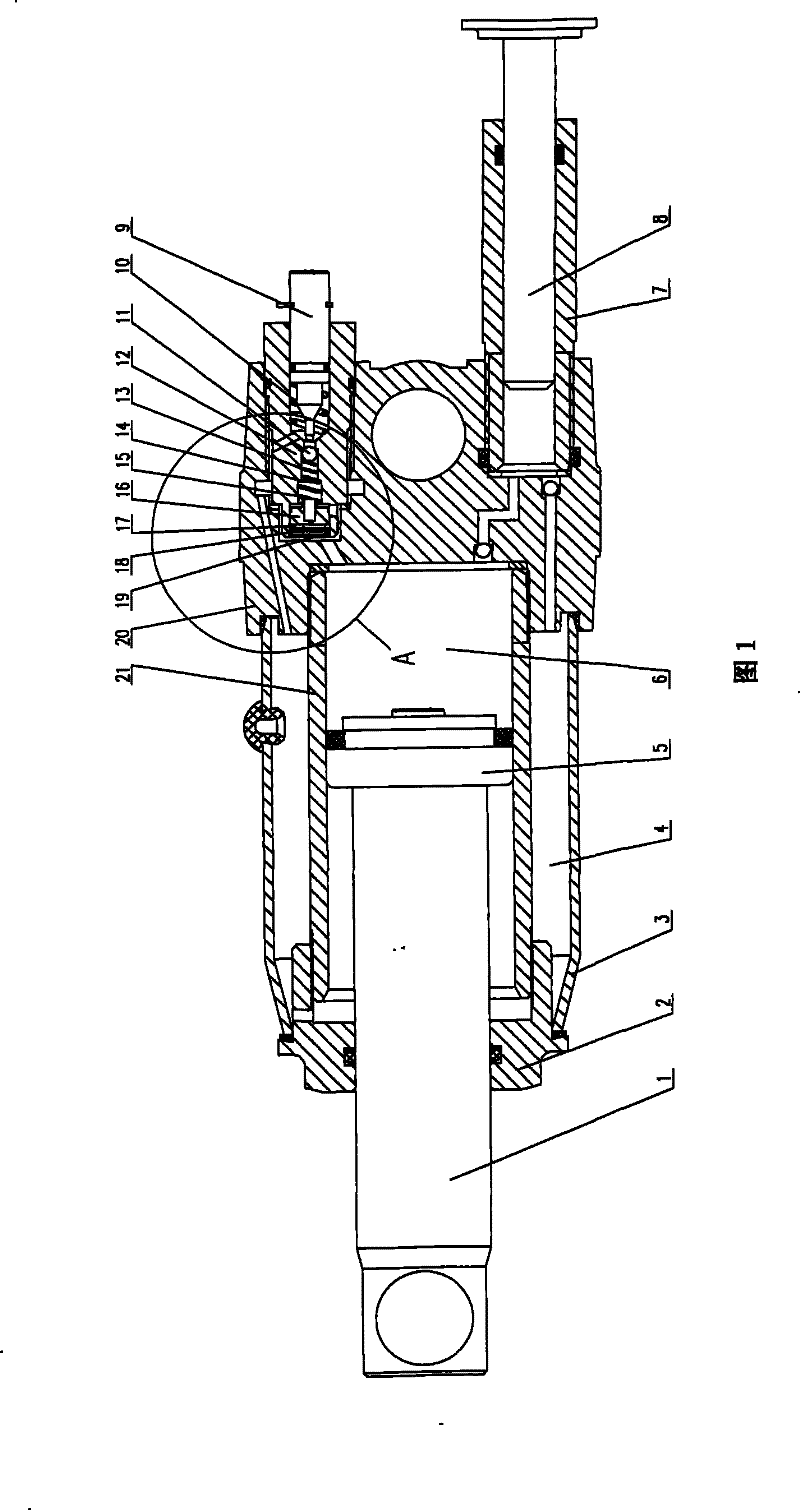
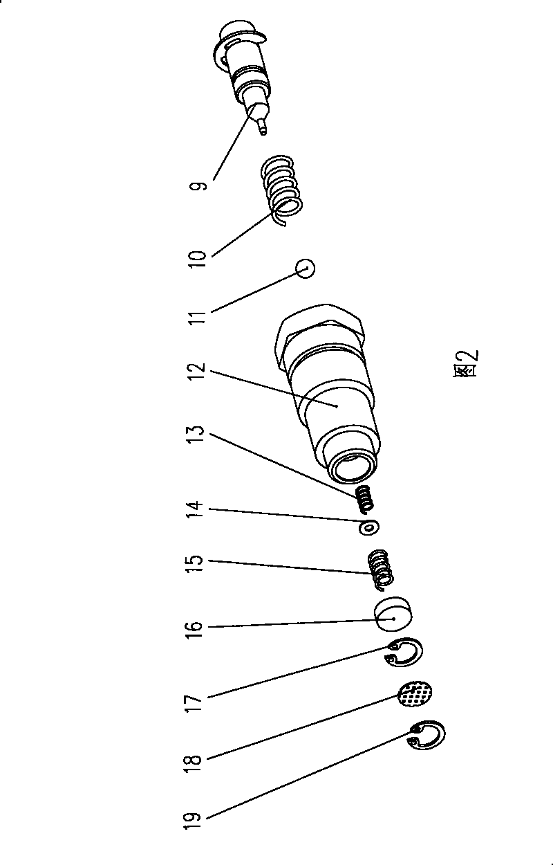
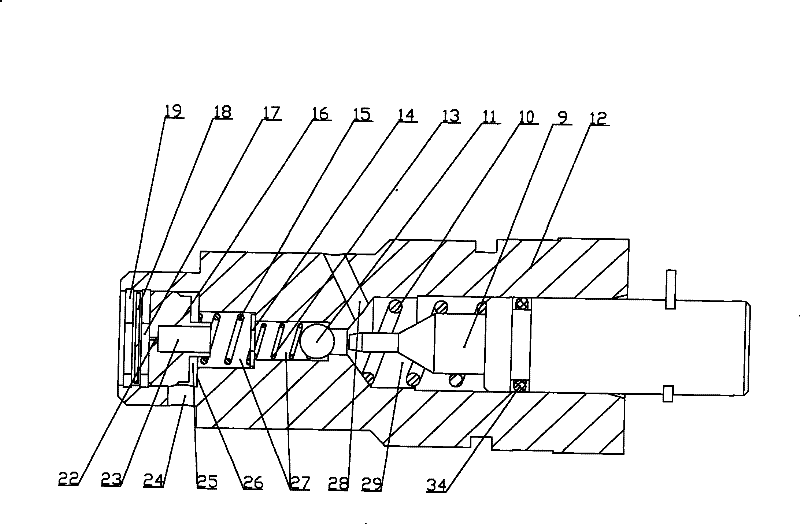
[0017] read on figure 1 , figure 2 , image 3 and Figure 4 , describing the working principle of the present invention: when the jack load returns, the oil return valve rod 9 is pushed to push away the steel ball 11. Since there is a pressure difference between the third pump chamber 30 and the valve chamber 23 of the throttle body 16, the first The pressure in the third pump chamber 30 is greater than the pressure in the valve chamber 23, pushing the throttle body 16 to overcome the spring force of the third spring 15 and forming a seal between the stepped surface 26 on the stepped hole 27 in the oil return valve body 12 Cooperate, so that the hydraulic medium in the cylinder chamber 6 passes through the third pump chamber 30→throttle hole 22 on the throttle valve body 16→valve chamber 23→stepped hole 27→ The second pump chamber 29 → the second oil passage 28 → the fourth pump chamber 33 → the fourth oil passage 32 returns to the oil storage chamber 4 . In the above lo...
PUM
 Abstract
Description
Claims
Application Information
 - R&D
- Intellectual Property
- Life Sciences
- Materials
- Tech Scout
- Unparalleled Data Quality
- Higher Quality Content
- 60% Fewer Hallucinations
Browse by: Latest US Patents, China's latest patents, Technical Efficacy Thesaurus, Application Domain, Technology Topic, Popular Technical Reports.
© 2025 PatSnap. All rights reserved.Legal|Privacy policy|Modern Slavery Act Transparency Statement|Sitemap|About US| Contact US: help@patsnap.com


