
An automated assembly tooling for antenna arrays

A technology of antenna array and assembly tooling, which is applied to antenna supports/installation devices, motor vehicles, lifting devices, etc., which can solve the problems of long preparation time for hoisting, waste of resources and costs, and inconvenient operation, and improve the convenience of operation , Ensure assembly efficiency and reduce the effect of hoisting and transshipment

Active Publication Date: 2021-11-26
BEIJING INST OF RADIO MEASUREMENT
View PDF12 Cites 0 Cited by
  • Summary
  • Abstract
  • Description
  • Claims
  • Application Information

AI Technical Summary

Problems solved by technology

[0003] (1) Each antenna requires a separate design of special assembly tooling, and there are no fully multi-purpose use scenarios, resulting in array adjustments in different assembly process steps and long hoisting preparation cycles, such as antenna arrays in manual assembly stations and automated assembly stations. It is necessary to change the tooling and re-hoist, fix, etc. during the transfer, and there is a waste of resources and costs
[0004] (2) The existing tooling and the front adopt a bolt-fastened installation structure. When hoisting, it is necessary to adjust and keep the mounting holes on both sides of the front frame fully matching with the multiple fixing holes on the tooling before installation. Due to the gap between the front frame and the tooling The matching gap between them is small, and there is a problem that the hoisting and positioning of the front is difficult. During the hoisting process, multiple people are required to repeatedly adjust the attitude of the front to ensure that all hole pairs can be installed in place. The entire hoisting process is time-consuming and laborious.
[0005] (3) The transfer of the antenna array at different stations is inconvenient, such as manual assembly-automated assembly-darkroom testing, etc., need to be hoisted and transferred repeatedly, the hoisting preparation time is long and unsafe
[0006] (4) The antenna array can only be installed and fixed in a vertical posture on the existing tooling, which can only ensure the basic accessibility of the workers' operation. It is inconvenient and inefficient for the workers to install the components in the bottom area of ​​the array

Method used


Image

  • An automated assembly tooling for antenna arrays
  • An automated assembly tooling for antenna arrays
  • An automated assembly tooling for antenna arrays

Examples


Embodiment Construction

[0035] The principles and features of the present invention are described below in conjunction with the accompanying drawings, and the examples given are only used to explain the present invention, and are not intended to limit the scope of the present invention.

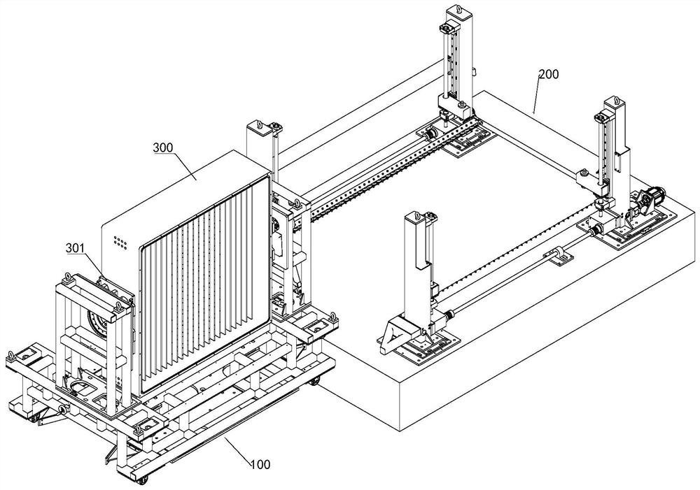
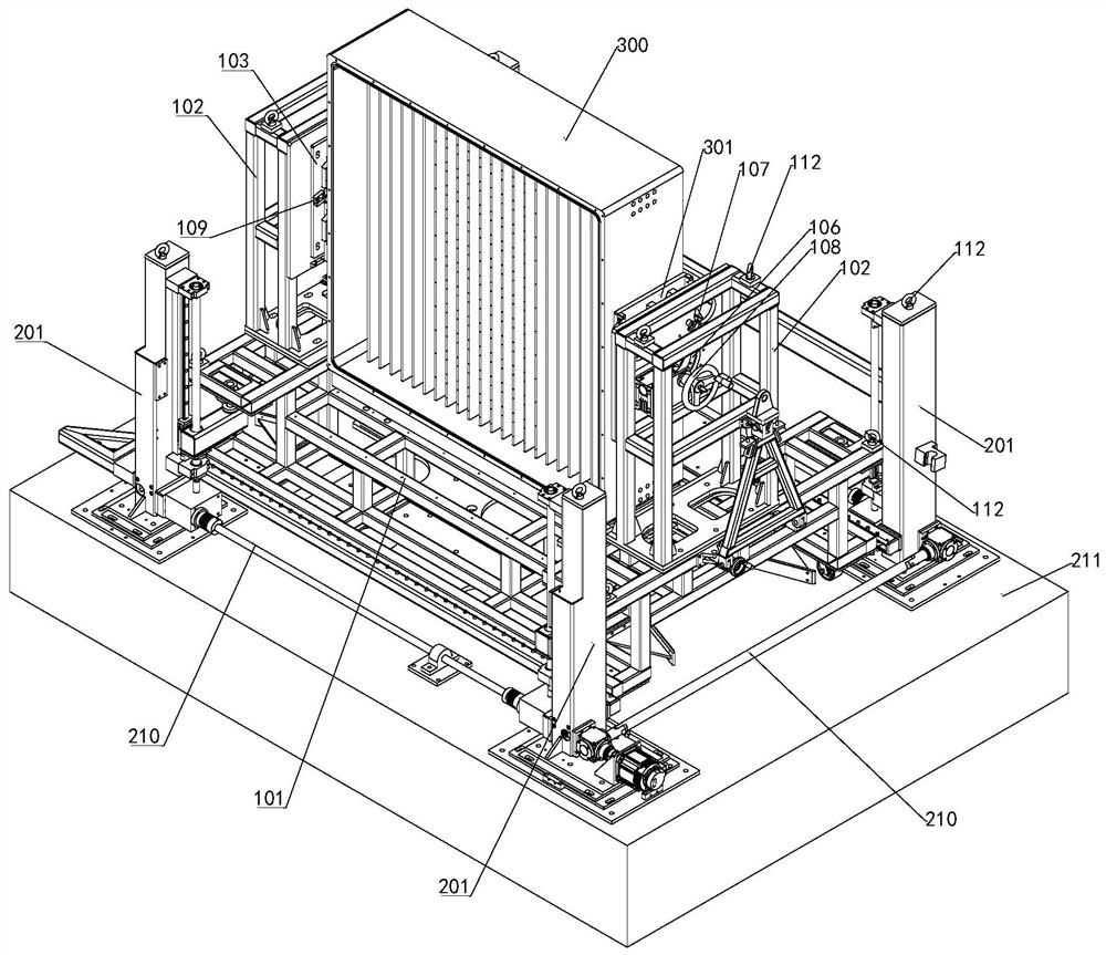
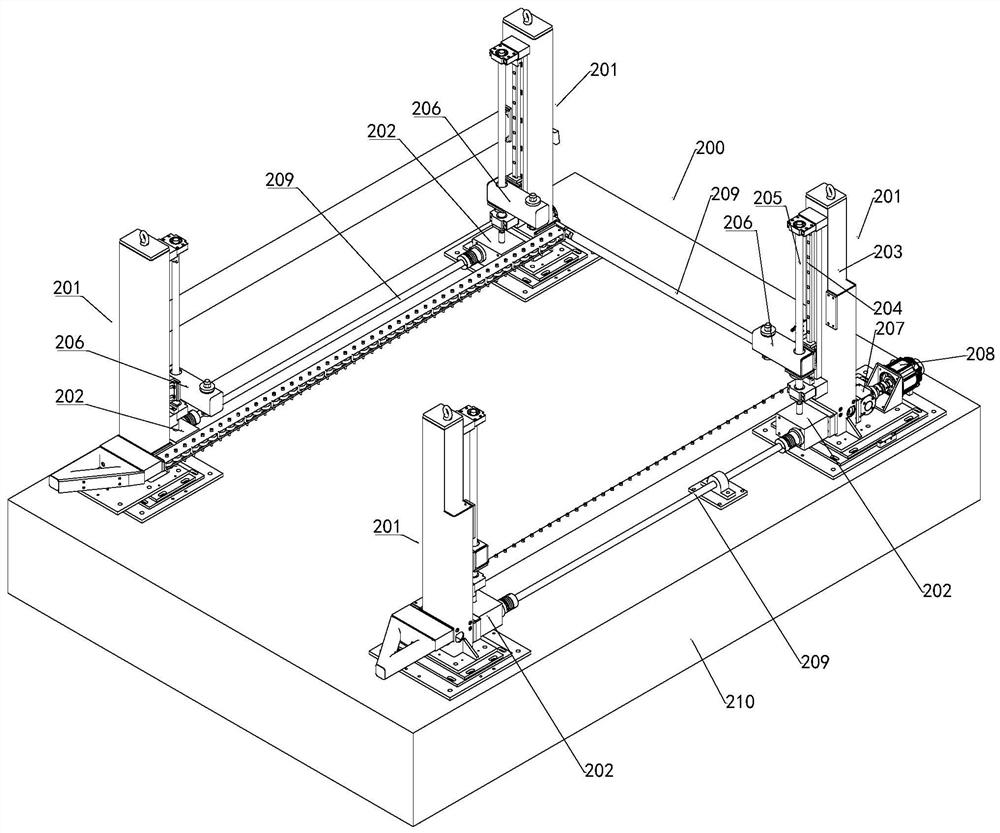
[0036] Such as Figure 1-Figure 4 As shown, an antenna array automatic assembly tool in this embodiment includes a movable transfer tool 100 and a lifting positioning tool 200. The transfer tool 100 includes a base 101 and a clamping part, and the clamping parts are two And symmetrically installed on the base 101, a space for assembling the antenna array 300 is reserved between the two clamping parts; the lifting and positioning tool 200 includes several independently arranged and mutually driven lifting parts 201, The transfer tool 100 can be moved between several lifting parts 201 and locked therewith.

[0037] Such as figure 1 , figure 2 and Figure 4 As shown, the clamping part of this embodiment includes a...


PUM


Abstract

The invention relates to an automatic assembly tool for an antenna array, which includes a movable transfer tool and a lifting positioning tool. The transfer tool includes a base and a clamping part, and the clamping parts are two and symmetrically installed on the base. , a space for assembling the antenna array is reserved between the two clamping parts; the lifting and positioning tooling includes several lifting parts that are independently arranged and mutually driven, and the transfer tooling can be moved between the several lifting parts And lock it in place. The antenna array automatic assembly tooling of the present invention reduces unnecessary hoisting and transfer of the antenna array during the assembly process, improves the safety of the assembly operation, improves the operation convenience of the antenna assembly, and ensures assembly efficiency.

Description

technical field [0001] The invention relates to the related technical field of phased array antenna assembly, in particular to a transfer, lifting and positioning tool used for radar array assembly. Background technique [0002] During the assembly and integration process of the phased array antenna, in order to ensure the support, transportation and attitude transformation of the phased array antenna, it is necessary to configure the phased array antenna assembly tooling. There are mainly the following problems in the use process of the existing array assembly tooling: [0003] (1) Each type of antenna needs to be individually designed with special assembly tooling, and there are no fully multi-purpose use scenarios, resulting in array adjustments in different assembly process steps and long hoisting preparation cycles, such as antenna arrays at manual assembly stations and automated assembly stations During the transfer, tooling needs to be changed, hoisted, fixed, etc., ...

Claims


Application Information

Patent Timeline
Patent Type & Authority Patents(China)
IPC IPC(8): B62B3/04B62B5/00B66F3/46B66F7/02B66F7/28H01Q1/12
CPCB62B3/04B62B5/00B62B2202/00B66F3/46B66F7/025B66F7/28H01Q1/12
Inventor 吉红伟卞玉柱熊强杨永真
Owner BEIJING INST OF RADIO MEASUREMENT
Learn More