
Paper feeding mechanism for flexible plate printer

A printing machine and paper feeding mechanism technology, applied in the direction of object supply, pile separation, thin material processing, etc., can solve the problems of unable to adjust the paper feeding module, time-consuming and laborious, troublesome equipment handling, etc., to achieve convenient paper feeding width, convenient Adjustment, structure simple effect

Inactive Publication Date: 2021-02-05
艾森思精密部件(长兴)有限公司
View PDF1 Cites 0 Cited by
  • Summary
  • Abstract
  • Description
  • Claims
  • Application Information

AI Technical Summary

Problems solved by technology

However, this equipment has the following problems: firstly, it is impossible to freely adjust the width of the paper feeding module and the size of the paper feeding port according to the size of the required printing materials; secondly, it is troublesome and time-consuming to change the equipment

Method used


Image

  • Paper feeding mechanism for flexible plate printer
  • Paper feeding mechanism for flexible plate printer
  • Paper feeding mechanism for flexible plate printer

Examples


Embodiment 1

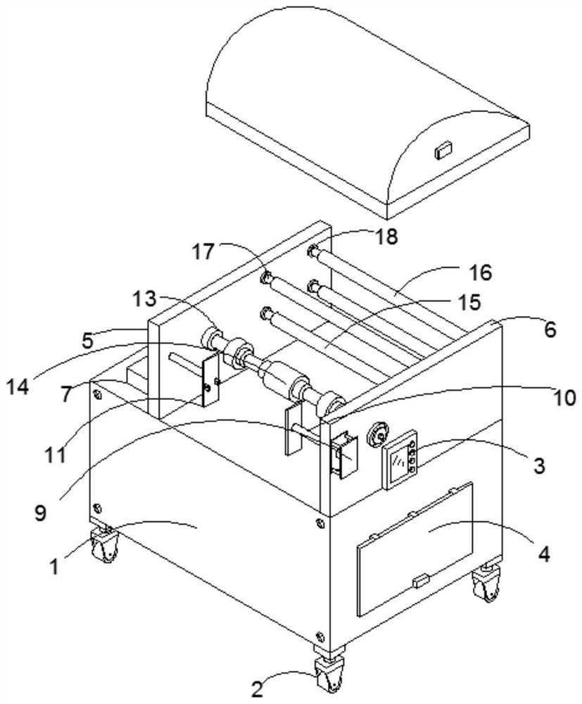
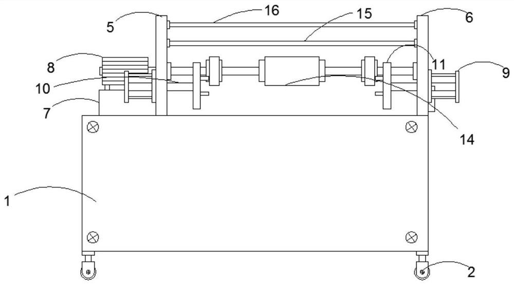
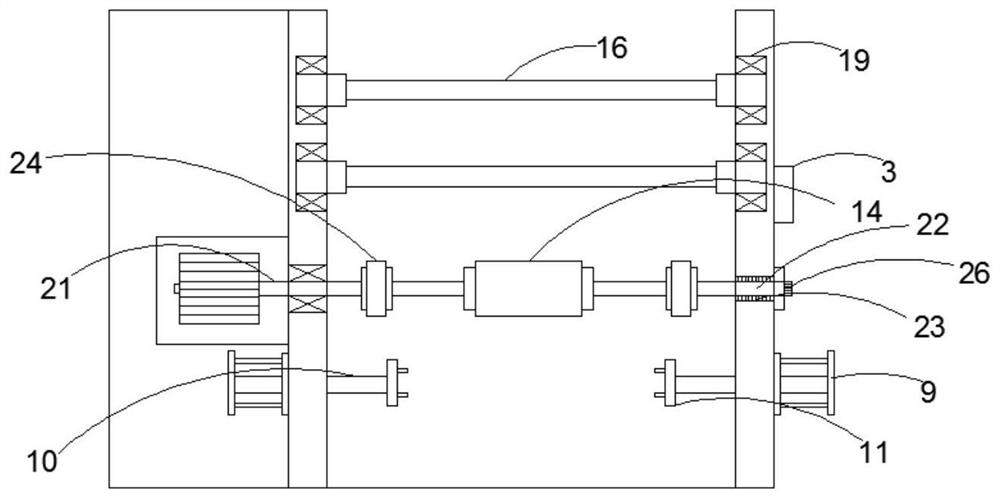
[0027] Such as Figure 1-3 As shown, the present invention provides a paper feeding mechanism for a flexo printing machine, including a workbench 1, self-locking universal wheels 2 are fixedly installed at the four corners of the bottom of the workbench 1, and one side of the workbench 1 is fixedly installed with A control module 3, a storage box 4 is provided at the bottom of the control module 3;

[0028] On the left side plate 5, a right side plate 6 is installed parallel to the right side of the left side plate 5, a support platform 7 is fixedly installed on one side of the left side plate 5, and a paper feeding motor 8 is fixedly placed on the top of the support platform 7, A hydraulic module 9 is fixedly installed on the front side of the left side plate 5, a hydraulic telescopic rod 10 is placed on one side of the hydraulic module 9, and a baffle 11 is fixedly installed on the top of the hydraulic telescopic rod 10;

[0029] Paper feeding module 12, described paper fee...

Embodiment 2

[0038] Such as Figure 1 to Figure 3 As shown, the parts that are the same as or corresponding to those in the first embodiment use the reference numerals corresponding to the first embodiment. For the sake of brevity, only the differences from the first embodiment will be described below. The difference between this embodiment two and embodiment one is: as image 3As shown, the leftmost end of the connecting shaft 23 and the rightmost end of the machine shaft 21 are provided with fixed disks 24, and the two fixed disks 24 are attached to the outsides of the left and right ends of the roller shaft 14 respectively. The rightmost end of 22 is connected with an operating gear 25, and the left and right ends of the two paper feed rollers A15 and the two paper feed rollers B16 are fixedly connected to the left side plate 5 and the right side plate 6 respectively through eight other fixed bearings, The paper feeding motor 8 is electrically connected to an external power source.

...


PUM


Abstract

The invention discloses a paper feeding mechanism for a flexible plate printer. The paper feeding mechanism comprises a workbench, a left side plate and a paper feeding module, wherein self-locking universal wheels are fixedly installed at four corners of the bottom of the workbench; a control module is fixedly installed at one side of the workbench; a storage box is arranged at the bottom of thecontrol module; a right side plate is arranged at the right side of the left side plate in parallel; a support table is fixedly installed at one side of the left side plate; a paper feeding motor is fixedly placed at the top of the support table; a hydraulic module is fixedly installed at the front side of the left side plate; a hydraulic telescopic rod is placed at one side of the hydraulic module; a baffle is fixedly installed at the top of the hydraulic telescopic rod; and the paper feeding module consists of the paper feeding motor, a fixed wheel and a roller shaft. Through the arrangementof detachable fixing disks, when printing materials of different specifications and different widths need to be printed, the paper feeding mechanism can be conveniently detached; and when a worker receives different printing requirements, the positions of the fixing disks can be conveniently changed, and the working efficiency is improved.

Description

technical field [0001] The invention relates to the technical field of flexographic printing machine equipment, in particular to a paper feeding mechanism for a flexographic printing machine. Background technique [0002] The flexographic printing machine uses fluid ink with strong fluidity. The ink is transferred to the graphic part of the printing plate by the ink fountain rubber roller and the anilox roller to make it inked, and then the printing pressure is applied by the pressure roller to press the printing plate on the printing plate. The ink is transferred to the substrate, and finally the printing process is completed through the drying surface. The printing part is the core of the flexographic printing machine. The arrangement of the printing part directly affects the operation performance, printing quality, printing speed and printing application range. According to the printing The arrangement of the parts can divide the flexographic printing machine into three t...

Claims


Application Information

Patent Timeline
Patent Type & Authority Applications(China)
IPC IPC(8): B65H5/06
CPCB65H5/06
Inventor 艾梁
Owner 艾森思精密部件(长兴)有限公司
Learn More