Textile machine and textile method
A technology of textile machines and components, which is applied in textiles, looms, textiles and papermaking, etc., and can solve the problem of fabrics with tight or loose lines that cannot be woven, single, and different gaps between lines that cannot be spun by a single textile machine Cloth and other problems, to achieve the effect of tight lines, avoid snagging or wrinkles, and avoid different degrees of tightness
- Summary
- Abstract
- Description
- Claims
- Application Information
AI Technical Summary
Problems solved by technology
Method used
Image
Examples
specific Embodiment approach 1
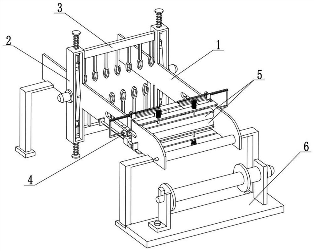
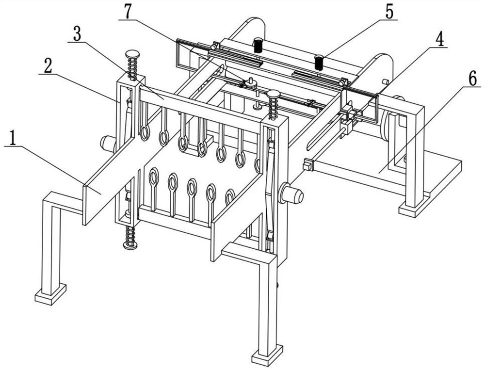
[0036] Combine below Figure 1-13 To illustrate this embodiment, the present invention relates to the technical field of textile machines, more specifically a textile machine, including a horizontal movement assembly 1, a cross drive assembly 2, a longitudinal cross assembly 3, a horizontal thread laying assembly 4, and a cloth smoothing assembly 5 , the cloth winding assembly 6 and the coil placement assembly 7, the cloth winding assembly 6 is connected to the front end of the horizontal movement assembly 1, and the two cross drive assemblies 2 are respectively connected to the left and right ends of the horizontal movement assembly 1, and the two longitudinal cross Components 3 are connected to two cross drive components 2, horizontal laying component 4 and horizontal moving component 1 are screwed together, and two cloth troweling components 5 are respectively connected to the upper and lower ends of horizontal laying component 4.
[0037]Two cross drive assemblies 2 drive ...
specific Embodiment approach 2
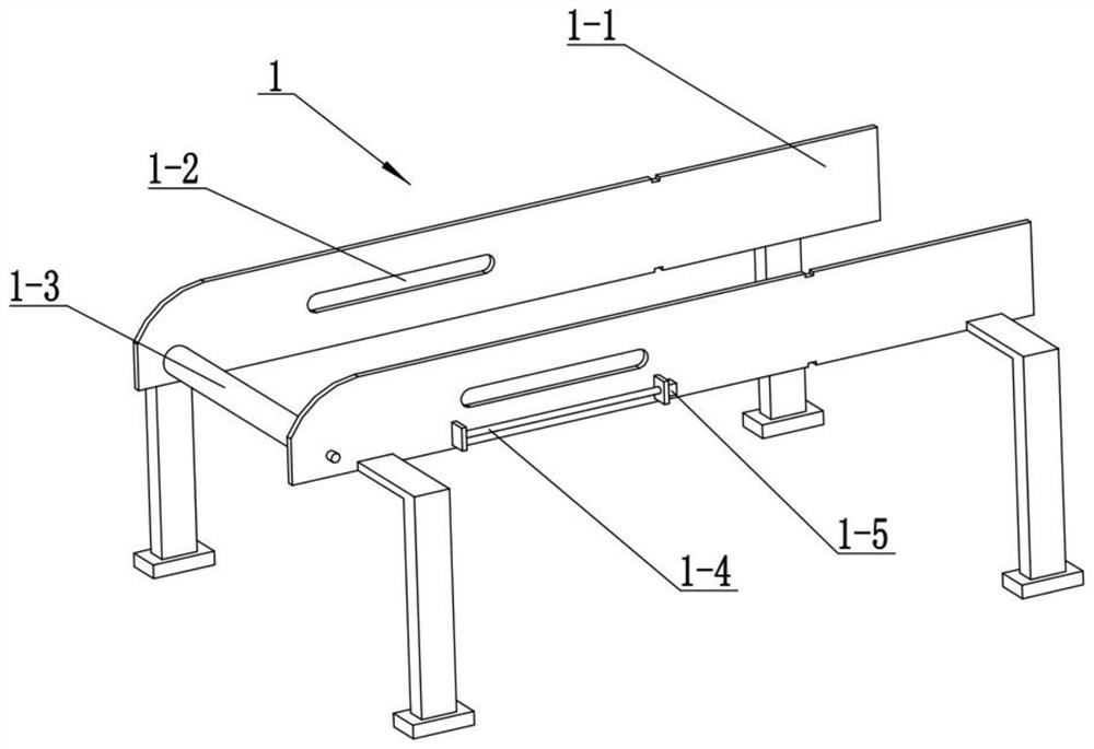
[0039] Combine below Figure 1-13 Describe this embodiment, this embodiment will further explain the first embodiment, the horizontal movement assembly 1 includes a support side plate 1-1, a horizontal slideway 1-2, a guide roller 1-3, a moving screw rod 1-4 and Horizontal motor 1-5, two support side plates 1-1 bottoms are provided with supporting legs, both support side plates 1-1 are provided with horizontal slideway 1-2, two moving screw rods 1-4 respectively Rotationally connected to the two supporting side plates 1-1, the two moving screw rods 1-4 are respectively fixedly connected to the output shafts of the two horizontal motors 1-5, and the two horizontal motors 1-5 are respectively fixedly connected to the two Support side panels 1-1.
specific Embodiment approach 3
[0041] Combine below Figure 1-13 Describe this embodiment, this embodiment will further explain the second embodiment, the cross drive assembly 2 includes a C-shaped longitudinal beam 2-1, a rotating motor 2-2, a symmetrical cam 2-3 and a longitudinal slideway 2-4 , the symmetrical cam 2-3 is fixedly connected to the output shaft of the rotary motor 2-2, the rotary motor 2-2 is fixedly connected to the C-shaped longitudinal beam 2-1, and the C-shaped longitudinal beam 2-1 is provided with two longitudinal slides Road 2-4, the two C-shaped longitudinal beams 2-1 are respectively fixedly connected to the two supporting side plates 1-1.
PUM
 Abstract
Description
Claims
Application Information
 - R&D
- Intellectual Property
- Life Sciences
- Materials
- Tech Scout
- Unparalleled Data Quality
- Higher Quality Content
- 60% Fewer Hallucinations
Browse by: Latest US Patents, China's latest patents, Technical Efficacy Thesaurus, Application Domain, Technology Topic, Popular Technical Reports.
© 2025 PatSnap. All rights reserved.Legal|Privacy policy|Modern Slavery Act Transparency Statement|Sitemap|About US| Contact US: help@patsnap.com


