
Concrete cutting device for highway construction

A cutting device and concrete technology, which is applied in the direction of roads, roads, road repairs, etc., can solve problems such as poor control, tired operation of construction personnel, and broken cutting pieces, so as to facilitate movement, avoid arm fatigue, and avoid damage to cutting pieces Effect

Pending Publication Date: 2021-02-05
CHINA MCC 2 GRP CO LTD
View PDF0 Cites 0 Cited by
  • Summary
  • Abstract
  • Description
  • Claims
  • Application Information

AI Technical Summary

Problems solved by technology

[0003] At present, there are many concrete cutting devices on the market, most of which are cut by artificial pressure or by means of an electric push rod. However, these concrete cutting devices have disadvantages: artificial pressure, long-term work will cause arm pain, construction It is tiring for personnel to operate; the electric push rod is used to apply pressure, the pressure is relatively large, it is not easy to control, and it is easy to cause the cutting blade to break

Method used


Image

  • Concrete cutting device for highway construction
  • Concrete cutting device for highway construction
  • Concrete cutting device for highway construction

Examples


Embodiment Construction

[0026] Various embodiments of the invention will be described in more detail below with reference to the accompanying drawings. In the various drawings, the same elements are denoted by the same or similar reference numerals. For the sake of clarity, various parts in the drawings have not been drawn to scale.

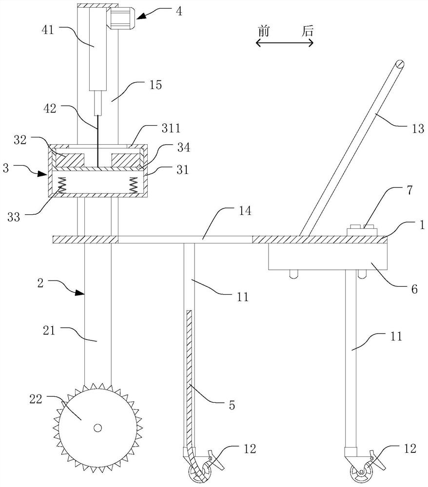
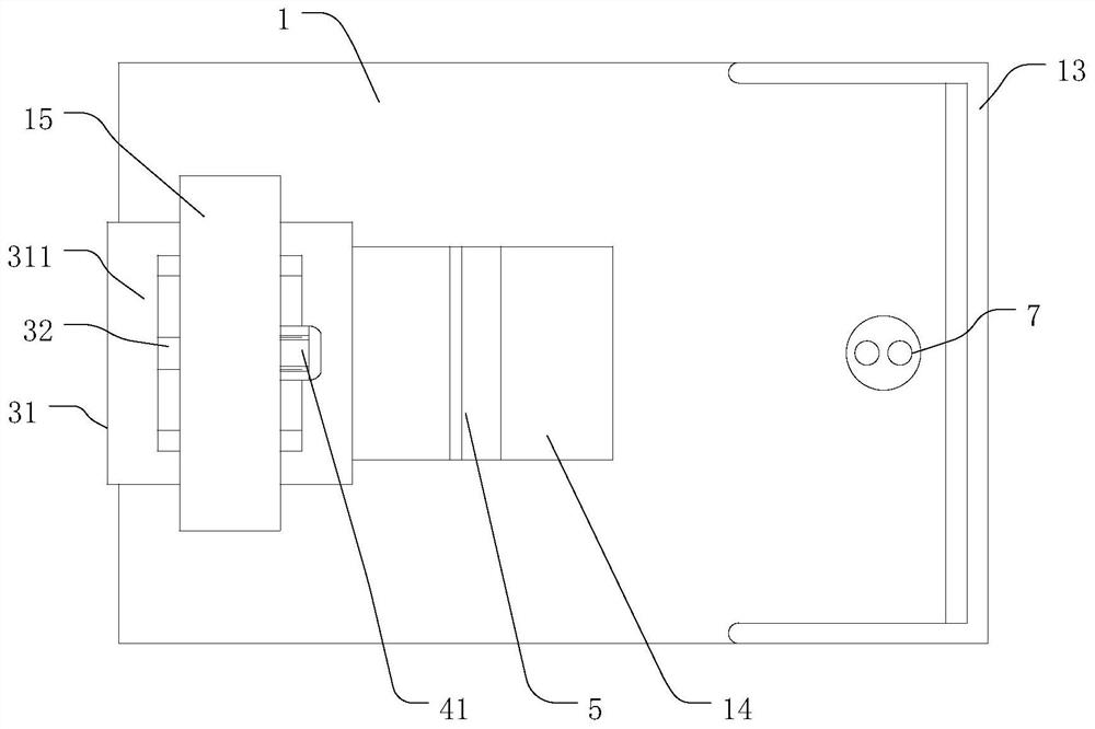
[0027] see Figure 1 to Figure 3 , The present invention provides a concrete cutting device for road construction, including a workbench 1, a cutting mechanism 2, a constant weight mechanism 3 and a lifting mechanism 4. The bottom of the workbench 1 is provided with a plurality of supporting legs 11 , and the bottom of each supporting leg 11 is provided with a roller 12 . The cutting mechanism 2 is slidably arranged on the front part of the workbench 1 up and down, and is used for cutting concrete. The constant weight mechanism 3 is fixedly connected to the upper end of the cutting mechanism 2 and is used to provide a constant downward pressure to the cutting mechani...


PUM


Abstract

The invention relates to a concrete cutting device for highway construction, comprising: a workbench, the bottom of the workbench is provided with a plurality of support legs, and the bottom of each support leg is provided with a roller; a cutting mechanism which is arranged at the front part of the workbench in an up-down sliding manner and is used for cutting concrete; a constant weight mechanism which is fixedly connected to the upper end of the cutting mechanism and used for providing downward constant pressure for the cutting mechanism; and a lifting mechanism which is arranged on the workbench and used for lifting or lowering the constant weight mechanism and the cutting mechanism. According to the concrete cutting device for highway construction, the cutting mechanism is arranged onthe front portion of the workbench in an up-down sliding mode, the constant weight mechanism is arranged on the upper portion of the cutting mechanism, when concrete is cut, the constant weight mechanism can provide downward constant pressure for the cutting mechanism, and the cutting mechanism does not need to be manually pressed, arm fatigue of constructors is avoided, and damage to the cuttingblade due to overlarge pressure is also avoided.

Description

technical field [0001] The invention relates to the technical field of road construction equipment, and more specifically, to a concrete cutting device for road construction. Background technique [0002] Concrete pavement refers to the pavement with cement concrete as the main material. Many highways and roads in cities and towns often use concrete as the pavement material. During the road construction process, the concrete pavement of the road is often cut. Concrete The cutting device is an indispensable construction equipment in the road construction process. [0003] At present, there are many concrete cutting devices on the market, most of which are cut by artificial pressure or by means of an electric push rod. However, these concrete cutting devices have disadvantages: artificial pressure, long-term work will cause arm pain, construction It is tiring for personnel to operate; the electric push rod is used to apply pressure, the pressure is relatively large, it is dif...

Claims


Application Information

Patent Timeline
Patent Type & Authority Applications(China)
IPC IPC(8): E01C23/09
CPCE01C23/0933
Inventor 王彦
Owner CHINA MCC 2 GRP CO LTD
Learn More