A pressurized coring system and method

A coring and core technology, which is used in the extraction of undisturbed core devices, earthwork drilling, drilling equipment, etc. The phenomenon of core cake formation, the effect of speeding up the drilling rate and improving the recovery factor

Active Publication Date: 2021-04-20
CHENGDU UNIVERSITY OF TECHNOLOGY
View PDF1 Cites 0 Cited by
  • Summary
  • Abstract
  • Description
  • Claims
  • Application Information

AI Technical Summary

Problems solved by technology

Although this patent is provided with a rock core pressure regulating structure, which can effectively ensure the integrity of the rock core by adjusting the pressure it receives, the structure of the device is complex, and its pressure adjustment is simply a work adjustment, which is difficult in deep formations and depths. In the case of changes, it takes a long time and a large amount of driving work to adjust the pressure on the core, which greatly increases the energy consumption of the device and the working time of the equipment. In addition, the core access structure in this structure cannot be quickly disassembled independently, which greatly increases the energy consumption of the device. Reduced the efficiency of core acquisition

Method used


Image

  • A pressurized coring system and method
  • A pressurized coring system and method
  • A pressurized coring system and method

Examples


Embodiment 1

[0039] In this application, when core sampling is carried out in the existing high in-situ stress environment, it is often impossible to obtain well-preserved core samples due to the stratum stress in which the rock mass is located. The initial in-situ stress is divided into for the following levels:

[0040] 1. Extremely high ground stress The maximum stress value of the vertical axis: ≥40MPa

[0041] Hard rock: During the excavation process, rockbursts sometimes occur, rock blocks pop up, the rock mass of the cave wall is peeled off, and there are many new cracks;

[0042] 2. High ground stress The maximum stress value of the vertical axis: 20-40MPa

[0043] Soft rock: The core of the drilled hole has a cake phenomenon, and the rock mass of the wall of the hole is peeled off during the excavation process, and the displacement is extremely significant, and even a large displacement occurs, which lasts for a long time and is not easy to form a hole; the rock mass of the found...

Embodiment 2

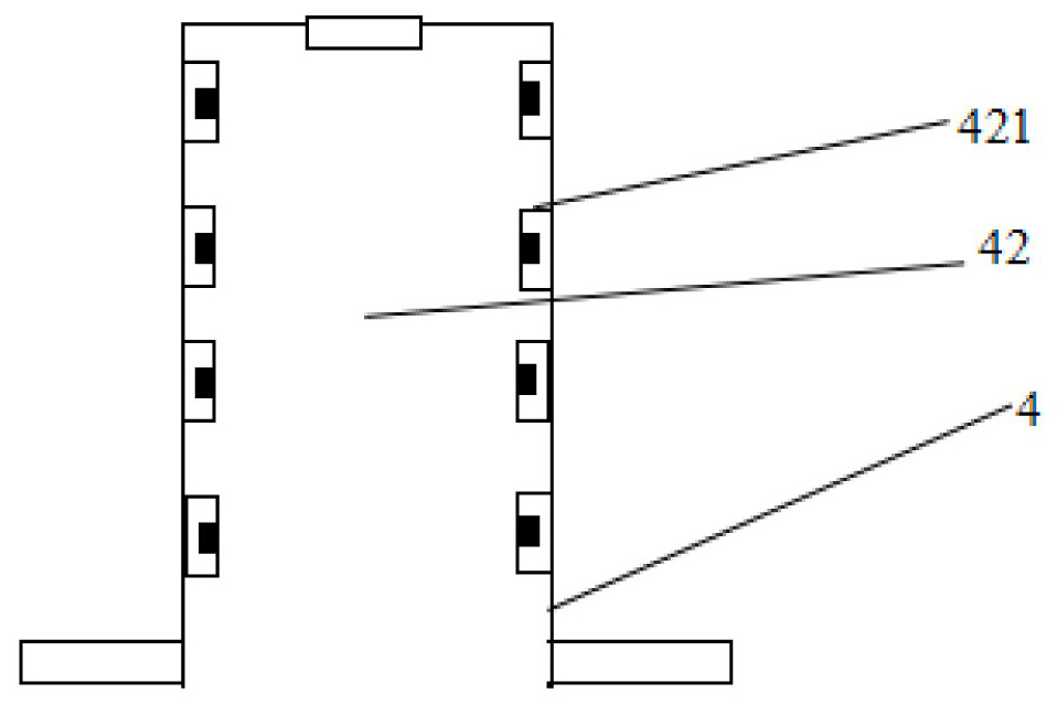
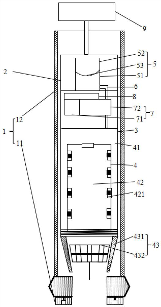
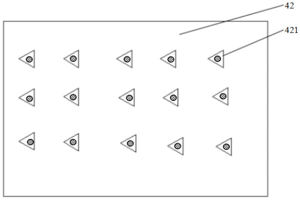
[0057] A pressurized coring system of the present application is especially suitable for performing stress-preserving coring work on rocks in a high ground stress environment. After the coring device collects the cores from the rock mass, the cores are inserted into the one-way sealed core chamber 42 made of high wear-resistant rubber sleeves, wherein the cores in the exposed part are processed by a certain pressure of the downhole mud. The stress is preserved, and the rock core wrapped by the rubber sleeve is transported a certain amount of high-pressure fluid into the high-pressure fluid chamber 41 through the micropump arranged on the core pipe 2 inside the drill pipe 12, so that the high-pressure fluid chamber 41 passes through the counter chamber. The expansion pressure of the wall is applied to the surface of the core wrapped by the rubber sleeve to apply the same pressure that the core was subjected to in the rock mass in the initial state, so as to realize the stress fi...


PUM


Abstract

The invention relates to a pressurized coring system. A liquid storage chamber is provided with a first liquid storage chamber and a second liquid storage chamber in such a way that the chamber of the liquid storage chamber is divided into two sub-chambers for storing different liquids through an elastic membrane, wherein, The first liquid storage chamber near the bottom of the liquid storage bin can store hydraulic fluid, and the second liquid storage chamber with the top wall of the liquid storage bin as the cavity wall can store drilling fluid for assisting the drill bit in drilling in the formation , the second liquid storage chamber can press the elastic film at the bottom according to the pressure change of the drilling fluid in the inner cavity, so that the elastic film is deformed into the first liquid storage chamber, and then compressed The hydraulic fluid is delivered to the high-pressure fluid chamber in accordance with the volume of the first liquid storage chamber.

Description

technical field [0001] The invention relates to the technical field of rock mass drilling and sampling, in particular to a pressurized coring system and method. Background technique [0002] In the exploration process of oil and gas reservoir development and deep underground engineering, because the deep rock mass is usually in a high geostress environment, the failure mechanism and mechanical properties of the actual rock mass are significantly different from those of the shallow rock. Therefore, When conventional drilling equipment performs core sampling operations in deep formations, the core samples are often unable to maintain their original structure and shape due to pressure changes and self-gravity stress changes during the ascent of the core tube, resulting in The occurrence of the core cake phenomenon makes it impossible for relevant operators to obtain complete and effective core samples, resulting in the inability of follow-up exploration personnel to make accura...

Claims


Application Information

Patent Timeline
Patent Type & Authority Patents(China)
IPC IPC(8): E21B25/08E21B25/02E21B10/02
CPCE21B25/08E21B25/02E21B10/02
Inventor 韦猛冯涛郑明明张广泽王凯王栋周珂锐徐正宣
Owner CHENGDU UNIVERSITY OF TECHNOLOGY
Why Eureka
Try Eureka