Hanging bracket for projector

A technology of projectors and hangers, which is applied in the direction of machines/supports, supporting machines, mechanical equipment, etc., can solve the problems of dust falling on the mirror surface, hidden safety hazards, inconvenient adjustment, etc., and achieves high degree of automation, wide applicability, and fast adjustment Effect

Active Publication Date: 2021-02-05
宁波高新区利威科技有限公司
View PDF7 Cites 1 Cited by
  • Summary
  • Abstract
  • Description
  • Claims
  • Application Information

AI Technical Summary

Problems solved by technology

[0004] The above-mentioned projector bracket has at least the following deficiencies in actual use: 1. It is inconvenient to adjust. Because it adopts the method of connecting pins to limit the position, when adjusting the lifting height, it needs to be manually adjusted by stepping on the height, which is inconvenient to adjust and has Potential safety hazard; 2. Although there is a frame, considering safety issues, the projector needs to be fixed by screws, and the projector needs to be removed during maintenance, otherwise there is a risk of the projector falling; 3. When not in use At the same time, at least two end faces of the projector are exposed to the air, and the mirror surface of the projection will be dusty, which will affect the projection effect; 4. It cannot meet people's needs for automation equipment

Method used


Image

  • Hanging bracket for projector
  • Hanging bracket for projector
  • Hanging bracket for projector

Examples


Embodiment 1

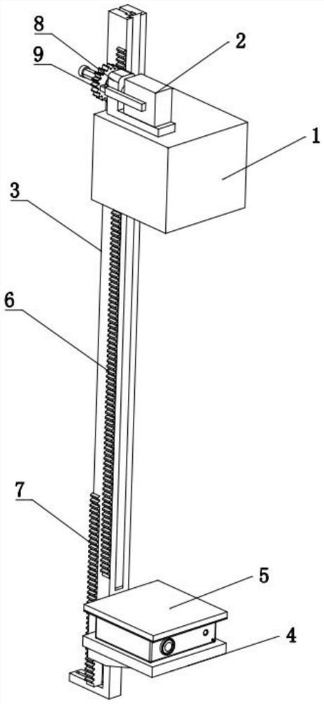
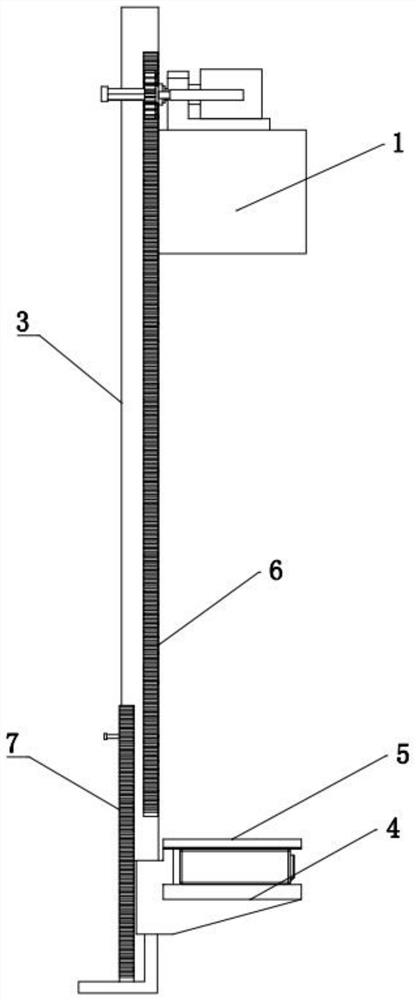
[0043] A hanger for a projector, refer to Figure 1-Figure 12 As shown, it includes a supporting part, a lifting part that lifts relative to the supporting part, and a fixing part located at the bottom of the lifting part for fixing the projector. The supporting part includes a dustproof box 1 that can fully accommodate the projector with an opening downward. The dustproof box 1 is fixed on a high place by screws.

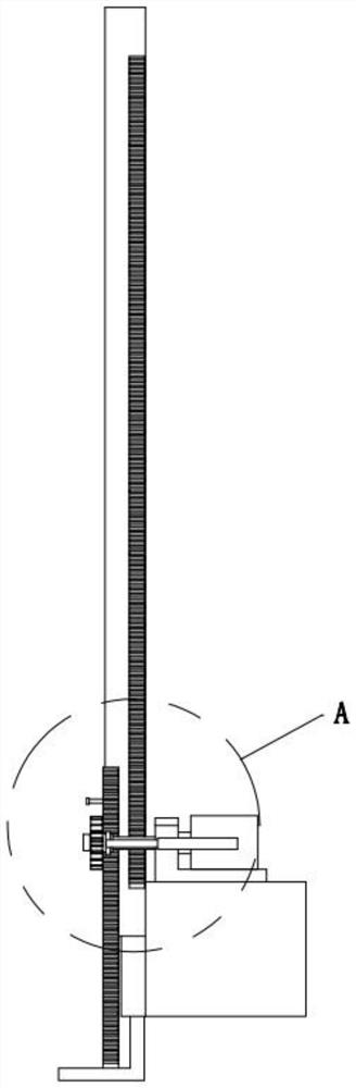
[0044] Lifting part reference Figure 1-Figure 7 As shown, it includes a lifting block 3, a first rack 6 positioned on one side of the lifting block 3, a first guide mechanism arranged between the lifting part and the dustproof box 1, a motor 2 arranged on the dustproof box 1, and The gear 9 arranged on the shaft of the motor 2 and meshed with the first rack 6 drives the lifting block 3 up and down, wherein the first guide mechanism includes a first slide vertically penetrating on the side of the lifting block 3 close to the dustproof box 1. The groove 101 and th...

Embodiment 2

[0057] The difference between this scheme and embodiment 1 is that, with reference to Figure 11 As shown, on the basis of Embodiment 1, a third return spring 29 is sleeved on the horizontal section of the second slider 13 of the second guide mechanism, and the coefficient of elasticity of the third return spring 29 is smaller than that of the second return spring. , when the second electromagnet 26 is energized and the pressing block 71 moves to the third groove 31 , the pressing block 71 is automatically snapped into the third groove 31 under the action of the third return spring 29 .

[0058] The advantage of the above arrangement is that once the pressing block 71 moves to the third groove 31, it can be automatically snapped into the third groove 31 under the action of the third return spring 29, which can be realized without precise program control. , and the elastic coefficient of the third back spring 29 is smaller than that of the second back spring because when the se...


PUM


Abstract

The invention relates to the technical field of projector projection equipment, and discloses a hanging bracket for a projector. The hanging bracket comprises a supporting part, a lifting part and a fixing part located at the bottom of the lifting part and used for fixing the projector, the lifting part comprises a lifting block, a first rack located on one side of the lifting block, a first guidemechanism arranged between the lifting part and a dustproof box, a motor arranged on the dustproof box, and a gear arranged on a motor shaft and meshed with the first rack to drive the lifting blockto ascend and descend, the fixing part comprises a bottom plate, a pressing plate and a self-adsorption mechanism arranged between the bottom and a matching block, the self-adsorption mechanism comprises a linkage mechanism, the linkage mechanism comprises a second rack, and a first driving mechanism is arranged between the motor shaft and the motor to realize extension and retraction of the gearso as to drive the gear to be independently meshed with the first rack to realize lifting of the projector or to be meshed with the second rack to realize adsorption fixation or desorption of the projector. The hanging bracket is high in automation degree and capable of achieving lifting of the projector and self-adsorption fixing or self-desorption dismounting of the projector.

Description

technical field [0001] The invention relates to the technical field of projector projection equipment, in particular to a projector hanger. Background technique [0002] The application of projectors has become very popular. For example, in conference rooms, classrooms and other places, projectors for their own use will be installed. These projectors are usually mounted by means of a pendant projector mount that secures them under a suspended ceiling. [0003] The Chinese patent with the notification number CN208459763U discloses a bracket for a projector, including a mounting plate, a hanger, a frame, a first mounting plate, a second mounting plate, a reflector frame and a reflector; The frame is mounted on the lower end of the hanger; the first mounting plate is mounted on the bottom of the frame, and the second mounting plate is mounted on the middle of the frame; the reflector frame is mounted on the frame On the side of the reflector, the reflector is installed on the...

Claims


Application Information

Patent Timeline
Patent Type & Authority Applications(China)
IPC IPC(8): F16M11/04F16M11/18G03B21/54B08B17/04
CPCF16M11/04F16M11/046F16M11/18B08B17/04G03B21/54
Inventor 应玉龙
Owner 宁波高新区利威科技有限公司
Why Eureka
Try Eureka