Teaching projection equipment based on information technology

A technology of projection equipment and technology, applied in projection devices, mechanical equipment, optics, etc., can solve the problems of low space utilization, difficulty in adjusting projection angle, and projector occupying desktop space, etc., to reduce energy consumption and friction. Effect

Pending Publication Date: 2021-02-05
苏州佩秋信息科技有限公司
View PDF8 Cites 0 Cited by
  • Summary
  • Abstract
  • Description
  • Claims
  • Application Information

AI Technical Summary

Problems solved by technology

[0003] With the continuous development and progress of society, information technology teaching is gradually developed, and projection equipment is needed in information technology teaching. Most of the existing projection equipment is used in conjunction with projectors and screens to achieve the purpose of projection. Now In the prior art, most projectors are fixed on the desktop or fixedly installed on the ceiling. Placing the projector on the desktop can facilitate the adjustment of its position and height, but it also makes the projector occupy a certain amount of space. In the desktop space, the space utilization rate is low, and the projector is directly fixed and installed on the indoor ceiling through bolts, and its projection angle is difficult to adjust. Therefore, the inventor has proposed a teaching projection device based on information technology after long-term research.

Method used


Image

  • Teaching projection equipment based on information technology
  • Teaching projection equipment based on information technology
  • Teaching projection equipment based on information technology

Examples


Embodiment Construction

[0027] In order to make the technical means, creative features, goals and effects achieved by the present invention easy to understand, the present invention will be further described below in conjunction with specific embodiments.

[0028] In the description of the present invention, it should be noted that the terms "upper", "lower", "inner", "outer", "front end", "rear end", "both ends", "one end", "another end" The orientation or positional relationship indicated by etc. is based on the orientation or positional relationship shown in the drawings, and is only for the convenience of describing the present invention and simplifying the description, rather than indicating or implying that the referred device or element must have a specific orientation, use a specific Azimuth configuration and operation, therefore, should not be construed as limiting the invention. In addition, the terms "first" and "second" are used for descriptive purposes only, and should not be understood ...


PUM


Abstract

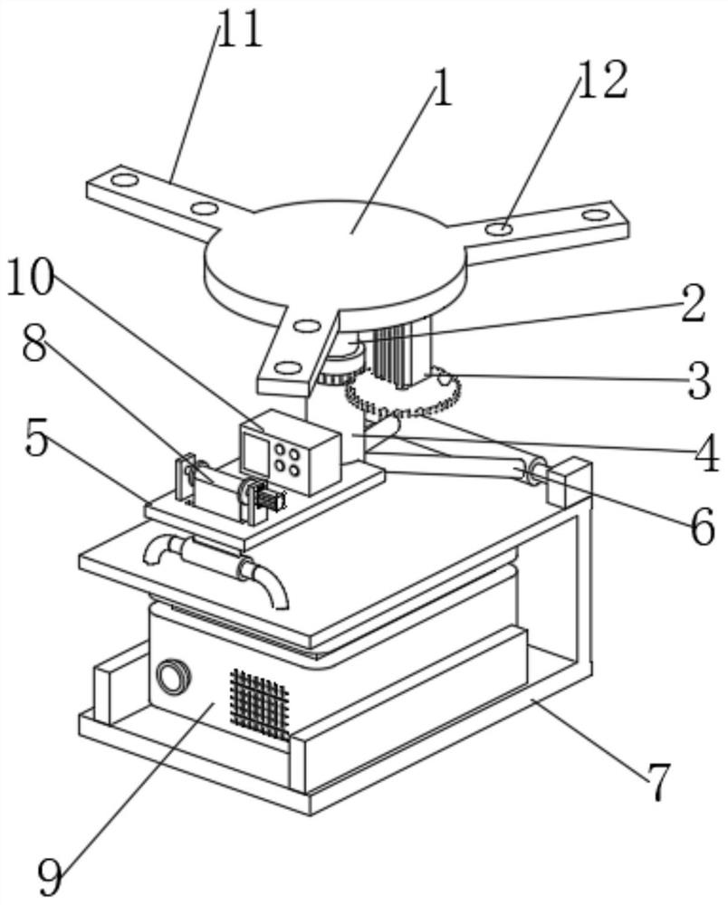
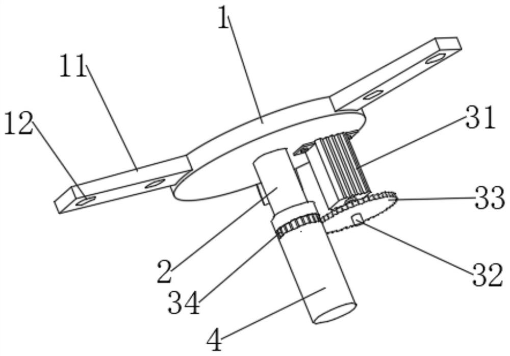
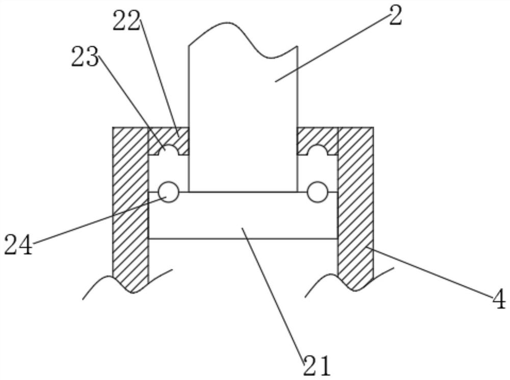
The invention discloses teaching projection equipment based on information technology. The teaching projection equipment comprises a mounting seat and a containing box, a vertical rod is fixedly mounted in the middle of the lower end of the mounting seat, an outer pipe is rotatably mounted at the lower part of the outer surface of the vertical rod, a driving device is mounted on one side of the lower end of the mounting seat, a movable connecting mechanism is arranged between the outer pipe and the containing box, a mounting plate is fixedly mounted on the side, away from the movable connecting mechanism, of the lower portion of the outer surface of the outer pipe, a lifting mechanism is arranged between the mounting plate and the containing box, the containing box is of a cuboid structurewith the two sides and the front end being open and the interior being communicating, a projector is placed in the containing box, three fixing plates are fixedly connected to the outer surface of the mounting seat in an annular array mode, and two vertically-through screw holes are formed in the upper ends of each of three fixing plates. According to the teaching projection equipment based on the information technology, the projection angle can be conveniently adjusted at multiple angles, actual operation is easy and convenient, the automation degree is high, and the teaching projection equipment is suitable for wide application and popularization.

Description

technical field [0001] The invention relates to the field of information technology equipment, in particular to a teaching projection device based on information technology. Background technique [0002] Information refers to the objects transmitted and processed by audio, news, and communication systems. It generally refers to all the content of human society. Human beings can distinguish different things by obtaining and identifying different information from nature and society, and can understand and transform the world. In all communication and In the control system, information is a form of universal connection. The society is accustomed to linking science and technology together, collectively referred to as science and technology, referred to as science and technology. In fact, the two are closely related and have important differences. Scientifically solve theoretical problems. , technology solves practical problems, and the problem that science needs to solve is to d...

Claims


Application Information

Patent Timeline
IPC IPC(8): F16M13/02F16M11/04F16M11/08F16M11/18F16M11/10G03B21/54
CPCF16M13/02F16M11/04F16M11/08F16M11/18F16M11/10G03B21/54
Inventor 李奕菲夏海燕
Owner 苏州佩秋信息科技有限公司
Why Eureka
Try Eureka