Power storage device

A technology for power storage devices and power storage components, which is applied in circuits, electrical components, secondary batteries, etc., and can solve problems such as sinking and battery system deflection

Pending Publication Date: 2021-02-05
GS YUASA INT LTD
View PDF1 Cites 0 Cited by
  • Summary
  • Abstract
  • Description
  • Claims
  • Application Information

AI Technical Summary

Problems solved by technology

[0003] However, when the battery system (power storage device) is installed, if the battery unit 102 is separated from the opposite surface facing the bottom surface of the battery unit 102 and both ends of the battery system (power storage device) are fixed, Then there is a risk that the central part between the two ends of the battery system will sink compared with the two ends of the battery system, that is, the battery system will be deflected.

Method used


Image

  • Power storage device
  • Power storage device
  • Power storage device

Examples


Embodiment Construction

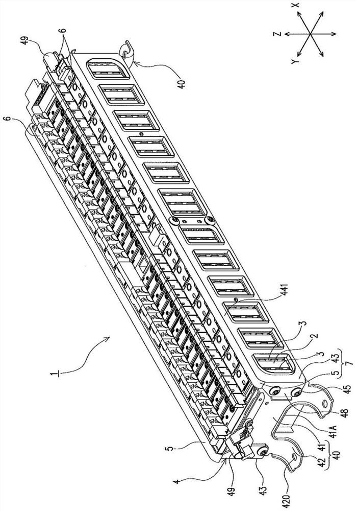
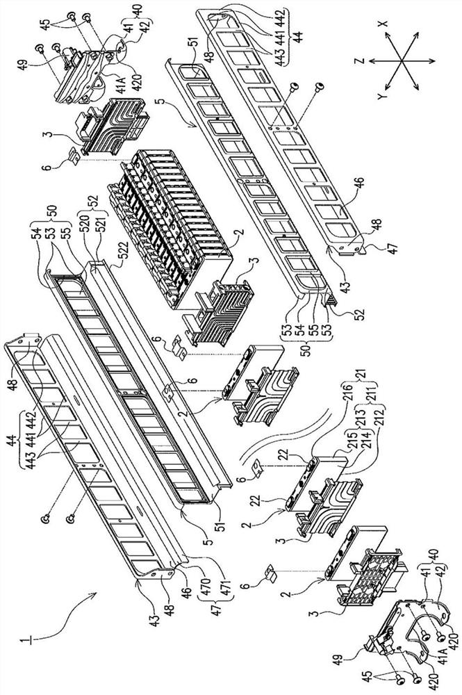
[0025] The power storage device of this embodiment includes:

[0026] a plurality of storage elements arranged in the first direction; and

[0027] a frame arranged along the plurality of storage elements;

[0028] Each of the plurality of storage elements has an outer surface facing a second direction orthogonal to the first direction,

[0029] The framework has:

[0030] a first location extending in the first direction along the outer surface; and

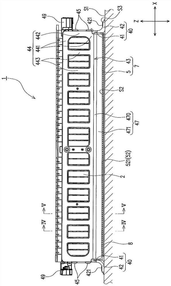
[0031] The second portion extends in the second direction from at least a part of the first portion toward an opposing surface on which the power storage device is provided.

[0032] According to this configuration, when the power storage device is installed, the second portion extends from the first portion toward the opposing surface facing the outer surface of the power storage element at a distance. Therefore, when the power storage device flexes or When the power storage device is about to be bent, the second portion ab...


PUM


Abstract

This power storage device is characterized by being provided with multiple power storage elements arranged in a first direction, and a frame which is arranged along the multiple power storage elements, wherein the power storage elements each has an outer surface facing in a second direction perpendicular to the first direction, and the frame has a first area which extends along the outer surface in the first direction, and a second area which, from at least one part of the first area, extends in the second direction towards an opposite surface where the power storage device is installed.

Description

technical field [0001] The present invention relates to an electrical storage device including a plurality of electrical storage elements arranged in a predetermined direction and a frame arranged along the plurality of electrical storage elements. Background technique [0002] Conventionally, there is known a battery system including a plurality of storage elements arranged in a predetermined direction and a frame arranged along the plurality of storage elements (for example, refer to Patent Document 1). Specifically, the battery system as Figure 8 As shown, a plurality of stacked battery cells 102 , a pair of end plates 140 arranged at both ends of the plurality of battery cells 102 , and connecting rods 143 arranged on both side surfaces of the plurality of battery cells 102 are provided. The connecting rod 143 has a belt shape, and fixes bent pieces provided by bending both ends of the battery cells 102 in the stacking direction inward to the end plate 140 . Thereby, t...

Claims


Application Information

Patent Timeline
IPC IPC(8): H01M50/209H01M50/244H01M50/291H01G11/12H01G11/78
CPCH01G11/12Y02E60/10H01G11/76H01M50/264H01G11/10H01G11/82H01M50/209H01M50/291H01M50/224H01M50/227H01M50/231H01M10/6555H01M10/6557H01M50/593
Inventor 西村洋介长绳伸之吉冈健太岁冈芳昌
Owner GS YUASA INT LTD
Why Eureka
Try Eureka