Bearing structure for device

A device and component technology, applied in the field of storage structure, can solve the problems of poor storage stability and low space utilization rate of containers, and achieve the effect of avoiding fixed drawer size, improving storage stability, and improving user experience

Pending Publication Date: 2021-02-09
GUANGDONG DTC HARDWARE PRECISION MFG CO LTD
View PDF1 Cites 2 Cited by
  • Summary
  • Abstract
  • Description
  • Claims
  • Application Information

AI Technical Summary

Problems solved by technology

[0003] The object of the present invention is to provide a storage structure for devices to overcome the problems of the prior art that the size of the drawer is fixed, only devices of a single size can be stored, the space utilization rate is low, and the storage stability of the containers is poor. Inadequacies

Method used


Image

  • Bearing structure for device
  • Bearing structure for device
  • Bearing structure for device

Examples


Embodiment Construction

[0036] The present invention will be further described below in conjunction with the accompanying drawings and embodiments.

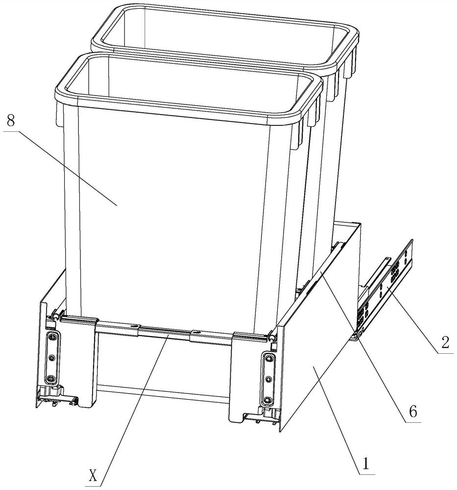
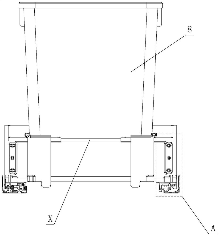
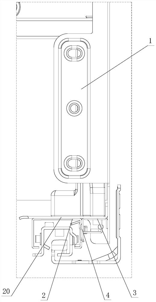
[0037] see Figure 1-Figure 14 , which is used for the receiving structure of the device, including side plates 1 and slide rail assemblies 2 arranged on the left and right, and is characterized in that: the lower parts of the left and right side plates 1 are respectively provided with supporting parts 3, and the left and right supporting parts 3 are respectively provided with relying parts 4 ; The side plate 1 is detachably installed on the slide rail assembly 2, and when the two are assembled, the slide rail assembly 2 relies on the inside of the relying part 4.

[0038] A receiving device is arranged between the left and right supporting parts 3, and the receiving device includes at least two front and rear cross-bar telescopic assemblies X which are arranged front and rear and can be positioned and moved laterally. Part 5, an upper supporting part an...


PUM


Abstract

The invention discloses a bearing structure for a device. The structure comprises a left side plate, a right side plate and a sliding rail assembly, supporting parts are arranged on the lower portionsof the left side plate and the right side plate respectively, and leaning parts are arranged on the left supporting part and the right supporting part respectively; the side plate is detachably arranged on the sliding rail assembly, and the sliding rail assembly leans against the inner side of the leaning part during assembly; a bearing device is arranged between the left supporting part and theright supporting part, the bearing devc comprises at least two front-back transverse rod telescopic assemblies which are arranged front and back and can transversely move in a positioning mode, front-back movable pieces transversely move on the front-back transverse rod telescopic assemblies respectively, an upper supporting and fixing part and a lower bearing part are arranged between the front-back movable pieces, the upper supporting and fixing part and/or the lower bearing part synchronously and transversely move along with the front-back moving part; at least one placeable device capableof being placed and a bearing area capable of adjusting the longitudinal and/or transverse size are formed between the front-back transverse rod telescopic assemblies and the movable pieces during movement; and the device is placed on the bearing area, the side part of the device is positioned and acted on the upper supporting part and/or the front-back transverse rod telescopic assembly, and thebottom of the device is positioned and supported on the lower bearing part.

Description

technical field [0001] The invention relates to a receiving structure for devices. Background technique [0002] The Chinese patent document number is CN111086803A, which discloses a drawer-type concealed trash can on May 1, 2020, which includes a trash can, a flat panel, a drawer guide rail and a connecting device, and the connecting device is either an L-shaped corner code or a wooden strip. It is said that the above-mentioned structure combines the trash can, flat panel and drawer guide rails into one. Usually the trash can is hidden in the vacant space under the furniture floor, and it is pulled out when it is needed, which eliminates the stumbling and unsightlyness of the trash can placed in the room Two big disadvantages; however, the size of the space in the kitchen is different, and the size of the drawers is designed according to the space in the kitchen. The size of the trash can is hidden, and its use is limited. At the same time, the trash can is positioned on ...

Claims


Application Information

Patent Timeline
Patent Type & Authority Applications(China)
IPC IPC(8): A47B88/40A47B88/407A47B88/90A47B88/919B65F1/00B65F1/14
CPCA47B2210/09A47B88/40A47B88/407A47B88/90A47B88/919A47B88/941B65F1/00B65F1/141
Inventor 伍志勇
Owner GUANGDONG DTC HARDWARE PRECISION MFG CO LTD
Why Eureka
Try Eureka