Centrifugal separation and extraction device for bioactive substances
A technology of biologically active substances and centrifugal separation, applied in the direction of centrifuges, etc., can solve the problems of low separation efficiency and affecting the extraction efficiency of the separation liquid, and achieve the effects of improving efficiency, automating the separation process, and accelerating efficiency
- Summary
- Abstract
- Description
- Claims
- Application Information
AI Technical Summary
Problems solved by technology
Method used
Image

Examples
Embodiment 1
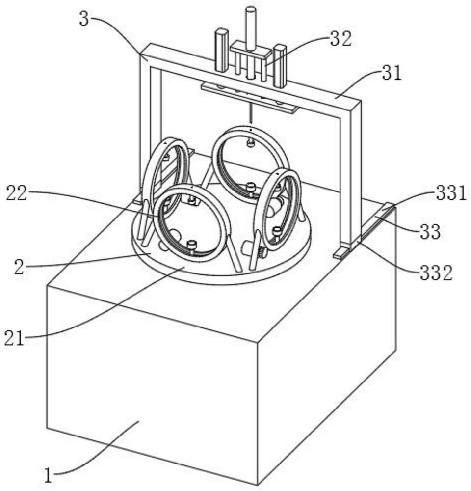
[0044] Such as Figure 1-Figure 7 As shown, a centrifugal separation and extraction device for biologically active substances includes a support box 1, and also includes a centrifugal mechanism 2 arranged on the support box 1. An extraction mechanism 3 is arranged on the rear side of the centrifugal mechanism 2. The extraction mechanism 3 and the support box 1 connection;
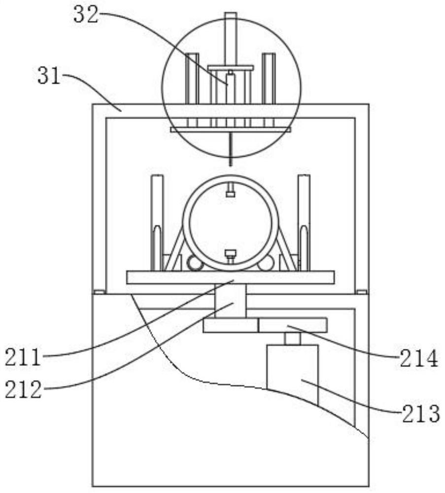
[0045]Centrifugal mechanism 2 comprises horizontal rotation mechanism 21, and vertical rotation mechanism 22 is evenly distributed on the upper end of horizontal rotation mechanism 21, and horizontal rotation mechanism 21 comprises rotating disc 211, and rotating disc 211 lower end center position is provided with rotating shaft 212, and supporting rotating disc 211 rotates, and rotating shaft 212 Through the upper end surface of the supporting box 1, the supporting box 1 is provided with a first motor 213, the output shaft of the first motor 213 and the lower end of the rotating shaft 212 are provided with...
Embodiment 2
[0049] Such as Figure 3-Figure 8 As shown, a centrifugal separation and extraction device for biologically active substances includes a support box 1, and also includes a centrifugal mechanism 2 arranged on the support box 1. An extraction mechanism 3 is arranged on the rear side of the centrifugal mechanism 2. The extraction mechanism 3 and the support box 1 connection;
[0050] Centrifugal mechanism 2 comprises horizontal rotation mechanism 21, and vertical rotation mechanism 22 is evenly distributed on the upper end of horizontal rotation mechanism 21, and horizontal rotation mechanism 21 comprises rotating disc 211, and rotating disc 211 lower end center position is provided with rotating shaft 212, and supporting rotating disc 211 rotates, and rotating shaft 212 Through the upper end surface of the supporting box 1, the supporting box 1 is provided with a first motor 213, the output shaft of the first motor 213 and the lower end of the rotating shaft 212 are provided wit...
PUM
 Abstract
Description
Claims
Application Information
 - R&D
- Intellectual Property
- Life Sciences
- Materials
- Tech Scout
- Unparalleled Data Quality
- Higher Quality Content
- 60% Fewer Hallucinations
Browse by: Latest US Patents, China's latest patents, Technical Efficacy Thesaurus, Application Domain, Technology Topic, Popular Technical Reports.
© 2025 PatSnap. All rights reserved.Legal|Privacy policy|Modern Slavery Act Transparency Statement|Sitemap|About US| Contact US: help@patsnap.com