Double-seal wear-resistant valve

A wear-resistant, double-sealing technology, applied to valve details, valve devices, valve housing structures, etc., can solve problems such as moss spreading and ball sealing degradation

Inactive Publication Date: 2021-02-09
广州凯宇信息技术有限公司
View PDF0 Cites 1 Cited by
  • Summary
  • Abstract
  • Description
  • Claims
  • Application Information

AI Technical Summary

Problems solved by technology

[0003] If the double-seal wear-resistant valve is installed in the middle of the pumping pipe of the outdoor water channel, moss will easily grow on the inner wall of the sphere after the water in the channel passes through the sphere inside the valve for a long time. The moss spreads to the inner wall of the ball and the valve, causing the valve to open again, and the outer wall of the ball and the inner wall of the valve will be crowded with moss, thereby reducing the sealing performance of the ball

Method used


Image

  • Double-seal wear-resistant valve
  • Double-seal wear-resistant valve
  • Double-seal wear-resistant valve

Examples


Embodiment 1

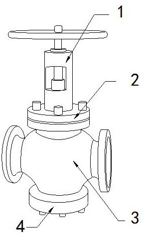
[0026] For example Figure 1-Figure 5 Shown:

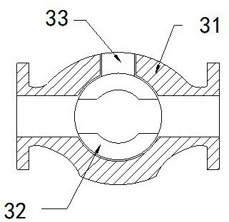
[0027] The invention provides a double-seal wear-resistant valve, the structure of which includes a control end 1, a connecting block 2, a valve body 3, and a connecting seat 4. The control end 1 is installed at the upper end of the connecting block 2, and the connecting block 2 Fixed on the upper end of the valve body 3, the valve body 3 and the connecting seat 4 are an integrated structure; the valve body 3 includes a shell 31, a ball 32, and a linkage shaft 33, and the ball 32 is movably engaged with the shell 31 In the inner position, the linkage shaft 33 passes through the shell 31 and is connected with the upper end of the ball 32 .

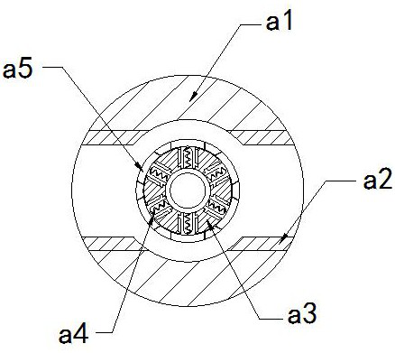
[0028] Wherein, the sphere 32 includes an outer frame a1, an inner frame a2, a ring body a3, a reset bar a4, and a clearing mechanism a5, the inner frame a2 and the outer frame a1 are an integrated structure, and the ring body a3 and the outer frame a1 The middle part of the clearing mechanis...

Embodiment 2

[0034] For example Figure 6-Figure 8 Shown:

[0035] Wherein, the built-in frame a2 includes a frame c1, a force plate c2, and a reset piece c3, the force plate c2 is movably engaged with the inner side of the frame c1, and the reset piece c3 is embedded and fixed in the force plate c2 and the frame c1 Between them, there are two stress plates c2, which are evenly distributed symmetrically on the inner walls of the upper and lower sides of the frame c1, and the force plate c2 can be pushed inward by the extrusion of the water flow on the stress plate c2. shrink.

[0036] Wherein, the stressed plate c2 includes a plate surface c21, a connecting rod c22, an outer pushing plate c23, and a sleeve frame c24. The lower end position of the sleeve frame c24, the sleeve frame c24 is movably engaged with the connecting rod c22, through the inertial force generated by the reset of the mechanism, the pusher plate c23 can slide downward along the connecting rod c22 under the cooperation...


PUM


Abstract

The invention discloses a double-seal wear-resistant valve which structurally comprises a control end, a connecting block, a valve body and a connecting base. The control end is mounted at the position of the upper end of the connecting block, the connecting block is fixed to the position of the upper end of the valve body, and the valve body and the connecting base are of an integrated structure.Water flow flowing through the interior of a sphere generates thrust on a ring body, thus the ring body can rotate along the internal center of an outer frame, a clearing mechanism can extend out along the ring body, until the clearing mechanism is attached to the inner wall of the outer frame, therefore a clearing brush can brush off mosses on the inner wall of the outer frame, and then the mosses brushed off are taken away together by the water flow. When the sphere is closed, By means of a resetting piece, a stress plate losing water flow extrusion can be pushed outwards to extend out to be reset, by means of inertia force generated by the stress plate, an outer pushing plate can extend out along a connecting rod under cooperation of a sleeve frame, and thus the outer pushing plate canpush away a moss layer attached to the bottom of the stress plate.

Description

technical field [0001] The invention relates to the field of valves, in particular to a double-seal wear-resistant valve. Background technique [0002] The double-seal wear-resistant valve is mainly used to control the opening and closing of the waterway. It is usually installed in the middle of the waterway pipeline. By turning the valve switch, the inner hollow ball can be turned to control the opening and closing of the waterway. Based on the above Description The inventors found that the existing double-seal wear-resistant valve mainly has the following deficiencies, for example: [0003] If the double-seal wear-resistant valve is installed in the middle of the pumping pipe of the outdoor water channel, moss will easily grow on the inner wall of the sphere after the water in the channel passes through the sphere inside the valve for a long time. The moss spreads to the inner wall where the ball and the valve fit together, and when the valve is opened again, the space be...

Claims


Application Information

Patent Timeline
IPC IPC(8): B08B1/00B08B9/055F16K5/06F16K5/08F16K27/06
CPCB08B1/00B08B9/0557B08B9/055F16K5/0605F16K5/08F16K27/067B08B1/12
Inventor 陈晓璇
Owner 广州凯宇信息技术有限公司
Why Eureka
Try Eureka