Hardware machining stamping device with protection mechanism and method of hardware machining stamping device

A technology of protection mechanism and stamping device, applied in the field of stamping equipment, can solve the problems of reducing the stamping efficiency of parts, damage of stamping device, lack of installation mechanism, etc., and achieve the effect of prolonging service life, ensuring safety, and scientific and reasonable structure.

Inactive Publication Date: 2021-02-09
雒贵平
View PDF7 Cites 3 Cited by
  • Summary
  • Abstract
  • Description
  • Claims
  • Application Information

AI Technical Summary

Problems solved by technology

[0004] The present invention provides a stamping device for metal processing with a protective mechanism and its method, which can effectively solve the problem that the current stamping device on the market proposed in the above background technology, in the actual use process, due to the lack of an installation mechanism, the staff in the It is time-consuming and labor-intensive to replace stamping plates of different specifications, which reduces the stamping efficiency of the staff. Moreover, due to the lack of a buffer mechanism, the impact force of the upper stamping device is too large during the stamping process, which may easily cause damage to the stamping device.

Method used


Image

  • Hardware machining stamping device with protection mechanism and method of hardware machining stamping device
  • Hardware machining stamping device with protection mechanism and method of hardware machining stamping device
  • Hardware machining stamping device with protection mechanism and method of hardware machining stamping device

Examples


Embodiment

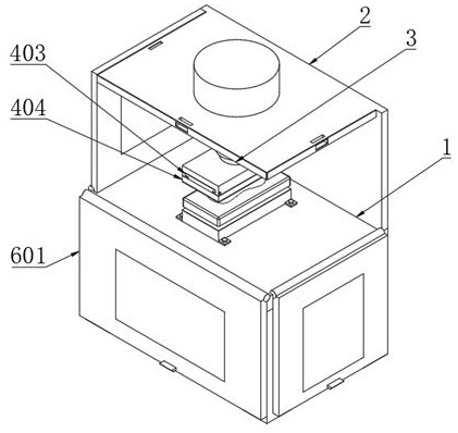
[0037] Example: such as Figure 1-4 As shown, the present invention provides a technical solution, a stamping device for metal processing with a protective mechanism, including a fixed base 1, a fixed baffle 2 is installed on the top edge of the fixed base 1, and a fixed baffle 2 is installed in the middle of the bottom end of the fixed baffle 2. There is a telescopic rod 3, and the bottom end of the telescopic rod 3 is provided with an installation mechanism 4;

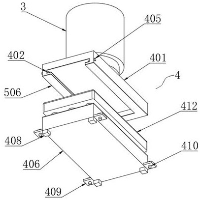
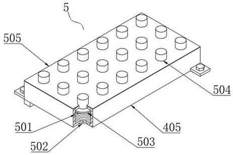
[0038] The mounting mechanism 4 comprises a fixed block 401, a T-shaped chute 402, a T-shaped slide block 403, an upper stamping plate 404, a fixed bolt 405, a fixed seat 406, a positioning groove 407, a positioning block 408, a positioning plate 409, a positioning bolt 410, and Box 411 and lower stamping plate 412;

[0039] In order to facilitate the staff to replace the upper stamping plate 404 and the lower stamping plate 412, a fixed block 401 is fixedly installed at the bottom end of the telescopic rod 3, and a...


PUM


Abstract

The invention discloses a hardware machining stamping device with a protection mechanism and a method of the hardware machining stamping device. The device comprises a fixing base, wherein a fixing baffle is installed on the edge of the top end of the fixing base, a telescopic rod is installed in the middle of the bottom end of the fixing baffle, and an installation mechanism is arranged at the bottom end of the telescopic rod. The installation mechanism comprises a fixing block, a T-shaped sliding groove, a T-shaped sliding block, an upper stamping plate, fixing bolts, a fixing seat, positioning grooves, positioning blocks, positioning plates, positioning bolts, a containing box and a lower stamping plate. Through the installation mechanism, the upper stamping plate and the lower stampingplate can be conveniently installed by workers, thus, the upper stamping plate and the lower stamping plate can be conveniently detached by the workers, then the difficulty of replacing the upper stamping plate and the lower stamping plate of different specifications by the workers is lowered, meanwhile, the replaced upper stamping plate and lower stamping plate can be conveniently placed by theworkers, and therefore the upper stamping plate and the lower stamping plate are prevented from being placed around.

Description

technical field [0001] The invention relates to the technical field of stamping equipment, in particular to a stamping device for metal processing with a protective mechanism and a method thereof. Background technique [0002] The stamping die used in the stamping device is a special process equipment for processing materials into parts in cold stamping processing. Stamping is to apply pressure to the material at room temperature by using the mold installed on the press to make it separate or plastic. Deformation, so as to obtain a pressure processing method of the required parts [0003] However, in the actual use of stamping devices currently on the market, due to the lack of installation mechanisms, it is time-consuming and laborious for staff to replace stamping plates of different specifications, thereby reducing the staff's stamping efficiency for parts. Moreover, due to the lack of buffer mechanism, resulting in excessive impact force of the upper punching device dur...

Claims


Application Information

Patent Timeline
Patent Type & Authority Applications(China)
IPC IPC(8): B21D37/04B21D55/00
CPCB21D37/04B21D55/00
Inventor 雒贵平
Owner 雒贵平
Why Eureka
Try Eureka