Large-size pipe surface rust removal device for pipe machining and rust removal method thereof
A mechanical processing and large-size technology, which is applied in the field of large-size pipe surface derusting devices for pipe machining, can solve the problems of inconvenient pipe rotation and inconvenience of rotating sandblasting and derusting, and achieves good results, smooth rotation, and improved applicability. sexual effect
- Summary
- Abstract
- Description
- Claims
- Application Information
AI Technical Summary
Problems solved by technology
Method used
Image
Examples
Embodiment 1
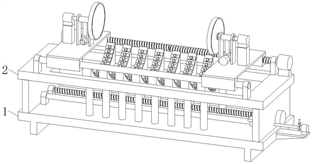
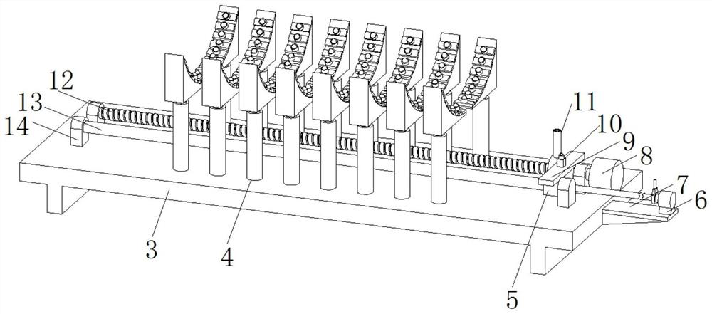
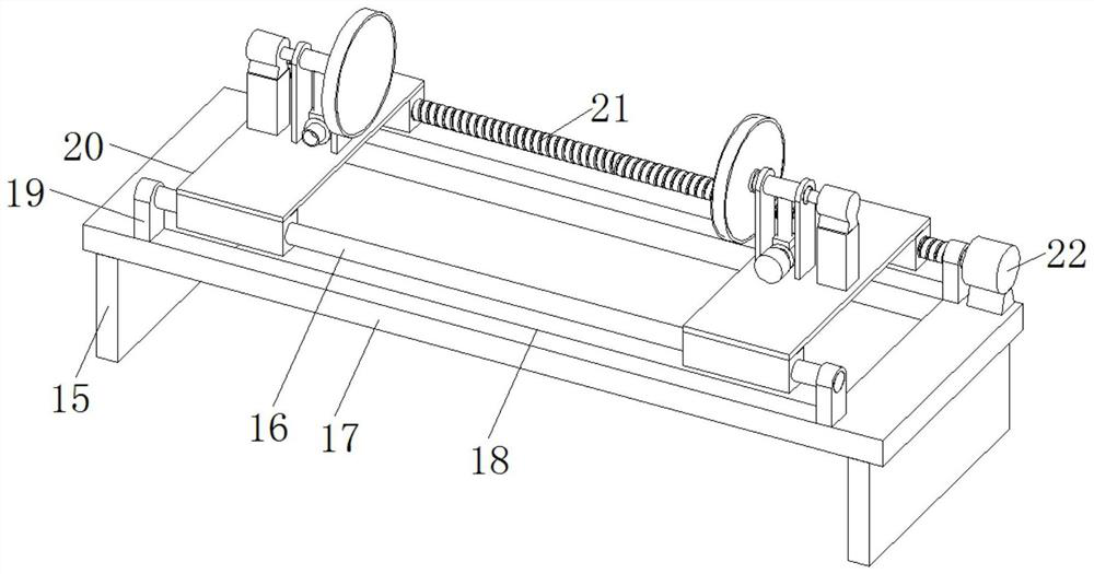
[0036] see Figure 1-8 , in an embodiment of the present invention, a large-size pipe surface derusting device for pipe machining includes a base assembly 1, a top assembly 2 is fixedly installed on the top of the base assembly 1, the base assembly 1 includes a base plate 3, and the base plate 3 Both sides of the top are welded and installed with two mounting parts-14, and threaded rod-12 and sliding rod-13 are respectively arranged between the two mounting parts-14 on both sides. The threaded rod-12 passes through the bearing and the mounting part-1. 14 rotating connection, fixedly connected between the slide rod one 13 and the mounting piece one 14, the driving end of the threaded rod one 12 is fixedly connected with the driving motor one 8, and the bottom of the driving motor one 8 is fixedly connected with the top of the base plate 3, the screw thread The outer walls of the rod one 12 and the slide rod one 13 are both covered with a transmission block one 5, and the tops o...
Embodiment 2
[0043] see Figure 1-8 , on the basis of Embodiment 1, the present invention provides a technical solution: the support structure 4 includes an electric telescopic rod 40, the movable end of the electric telescopic rod 40 is fixedly connected with a mounting seat 41, and the top of the mounting seat 41 is provided with an arc On the surface, a number of mounting plates 42 are fixedly installed on the arc surface of the mounting seat 41 at equal distances, and the middle part of the top of the mounting plate 42 is fixedly mounted with universal balls 43 .
[0044] When the pipe is placed, the support structure 4 can support the pipe from the bottom, thereby improving the stability of the pipe placement and the operation stability of the device, and the setting of the universal ball 43 makes the pipe and the support structure 4 The contact between them is rolling contact, the friction coefficient is low, and the pipe rotates more smoothly.
Embodiment 3
[0046] see Figure 1-8 , On the basis of Embodiment 1 and Embodiment 2, the present invention provides a technical solution: the side of the transmission plate 9 away from the high-pressure pump material structure 6 is fixedly installed with a desanding structure 11, and the desanding structure 11 includes a standpipe 34 , the inner cavity of the standpipe 34 is fixedly equipped with an air inlet mechanism 33, and the air outlet end of the air inlet mechanism 33 is fixedly connected with the air inlet end of the arc-shaped air outlet ring 35, and the inner wall of the arc-shaped air outlet ring 35 is equidistantly opened. There are several through holes-36.
[0047] The air intake mechanism 33 includes a fixed sleeve 38, the inner cavity of the fixed sleeve 38 is fixedly equipped with a driving motor 37, and the driving shaft of the driving motor 37 is fixedly connected with a fan blade 39.
[0048] The drive plate-9 also drives the desanding structure 11 to move when moving ...
PUM
 Abstract
Description
Claims
Application Information
 - R&D
- Intellectual Property
- Life Sciences
- Materials
- Tech Scout
- Unparalleled Data Quality
- Higher Quality Content
- 60% Fewer Hallucinations
Browse by: Latest US Patents, China's latest patents, Technical Efficacy Thesaurus, Application Domain, Technology Topic, Popular Technical Reports.
© 2025 PatSnap. All rights reserved.Legal|Privacy policy|Modern Slavery Act Transparency Statement|Sitemap|About US| Contact US: help@patsnap.com


