
Hydraulic mechanical arm facilitating stable angle adjustment and having grabbing force feedback function

A hydraulic machinery and angle technology, which is applied in the direction of manipulators, program-controlled manipulators, claw arms, etc., can solve problems such as inconvenient angles, instability, and stable adjustments, and achieve convenient and stable angle adjustments, prolong service life, and increase stability. Effect

Pending Publication Date: 2021-02-09
STATE GRID SHANXI ELECTRIC POWER COMPANY CHANGZHIELECTRIC POWER SUPPLY
View PDF0 Cites 3 Cited by
  • Summary
  • Abstract
  • Description
  • Claims
  • Application Information

AI Technical Summary

Problems solved by technology

[0004] The purpose of the present invention is to provide a hydraulic mechanical arm that is convenient for stable angle adjustment and has grasping force feedback. And it is inconvenient to adjust the angle stably, the grasping force cannot be adjusted, and the grasped material cannot be protected to prevent material damage caused by excessive grasping force. At the same time, the instability of the angle adjustment will cause the material to fall and be damaged. Unable to meet the needs of users, reducing the practicality of hydraulic manipulators

Method used


Image

  • Hydraulic mechanical arm facilitating stable angle adjustment and having grabbing force feedback function
  • Hydraulic mechanical arm facilitating stable angle adjustment and having grabbing force feedback function
  • Hydraulic mechanical arm facilitating stable angle adjustment and having grabbing force feedback function

Examples


Embodiment Construction

[0022] In order to enable those skilled in the art to better understand the technical solution of the present invention, the present invention will be described in detail below in conjunction with the accompanying drawings. The description in this part is only exemplary and explanatory, and should not have any limiting effect on the protection scope of the present invention. .

[0023] It should be noted that like numerals and letters denote similar items in the following figures, therefore, once an item is defined in one figure, it does not require further definition and explanation in subsequent figures.

[0024] It should be noted that the orientation or positional relationship indicated by the terms "center", "upper", "lower", "left", "right", "vertical", "horizontal", "inner" and "outer" are Based on the orientation or positional relationship shown in the drawings, or the orientation or positional relationship that the inventive product is usually placed in use, it is onl...


PUM


Abstract

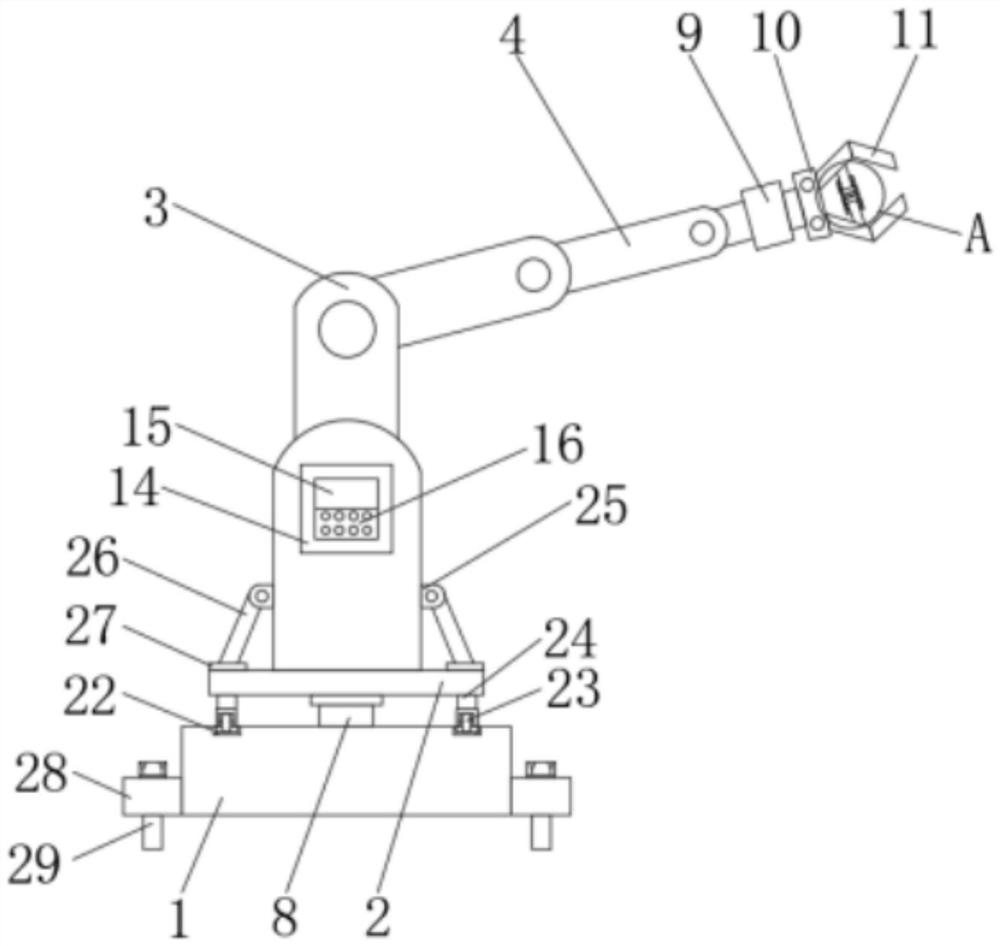
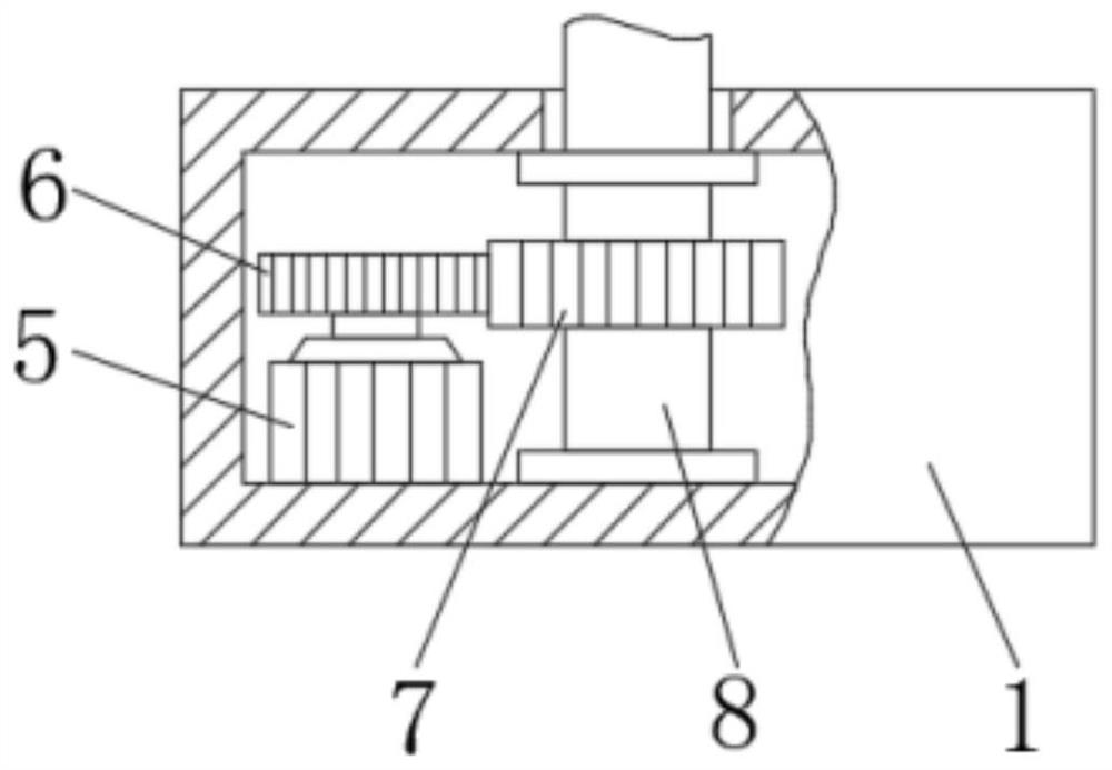
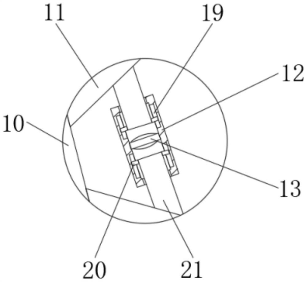
The invention discloses a hydraulic mechanical arm facilitating stable angle adjustment and having the grabbing force feedback function. The hydraulic mechanical arm facilitating stable angle adjustment and having the grabbing force feedback function comprises a base, a fixing plate, an electric push rod and a movable arm, and a motor is fixedly connected to the left side of the bottom of an innercavity of the base. According to the hydraulic mechanical arm facilitating the stable angle adjustment and having the grabbing force feedback function, through arrangement of the base, the fixing plate, the electric push rod, the movable arm, the motor, a driving gear, a driven gear, a driving shaft, a micro hydraulic cylinder, a connecting plate, a grabbing claw, a fixing shell, a pressure sensor, a controller, a display screen, a control panel, a processor, a heat dissipation opening, a first sliding groove, a first sliding block, a movable column, an arc-shaped sliding groove, sliding wheels, supports, installing blocks, pulling rods, connecting blocks, installing bases, installing pins and alarms, the beneficial effects that grabbing force feedback is achieved, and stable angle adjustment is convenient are achieved, and the problems that an existing hydraulic mechanical arm does not have the grabbing force feedback function, stable angle adjustment is inconvenient, the grabbing force cannot be adjusted, and grabbed materials cannot be protected are solved.

Description

technical field [0001] The invention relates to the technical field of hydraulic mechanical arms, in particular to a hydraulic mechanical arm that is convenient for stable angle adjustment and has grasping force feedback. Background technique [0002] The mechanical arm is a mechatronic device that anthropomorphizes the functions of the arm, wrist and hand. The operation requirements of industrial production, such as clamping welding tongs or torches, performing spot welding or arc welding on automobile or motorcycle bodies, handling die-casting or stamping parts or components, performing laser cutting, spraying, assembling mechanical parts, etc. Wait. [0003] At present, the existing hydraulic mechanical arm does not have grasping force feedback and is inconvenient to adjust the angle smoothly. It is impossible to adjust the grasping force, and it cannot protect the grasped materials to prevent material damage caused by excessive grasping force. , At the same time, insta...

Claims


Application Information

Patent Timeline
IPC IPC(8): B25J9/16B25J18/00
CPCB25J9/1633B25J9/161B25J18/00
Inventor 彭孝荣张军六宁忠荣唐保国姚劲松宋宁宁魏鑫付敏翟永庆肖斌郭晓程
Owner STATE GRID SHANXI ELECTRIC POWER COMPANY CHANGZHIELECTRIC POWER SUPPLY
Learn More