
Steam curing device for prefabricated part

A technology of prefabricated components and steam curing, applied in the direction of manufacturing tools, ceramic molding machines, etc., to achieve the effect of reducing requirements, reducing cross-flow of sewage, and reducing labor intensity

Pending Publication Date: 2021-02-09
南通齐鑫电气自动化科技有限公司
View PDF0 Cites 1 Cited by
  • Summary
  • Abstract
  • Description
  • Claims
  • Application Information

AI Technical Summary

Problems solved by technology

[0003] The technical problem to be solved by the present invention is to change the natural maintenance mode of traditional prefabricated components, provide an automatic maintenance device for prefabricated components, improve the maintenance speed of prefabricated components, and reduce manual participation in the maintenance process

Method used


Image

  • Steam curing device for prefabricated part
  • Steam curing device for prefabricated part

Examples


Embodiment Construction

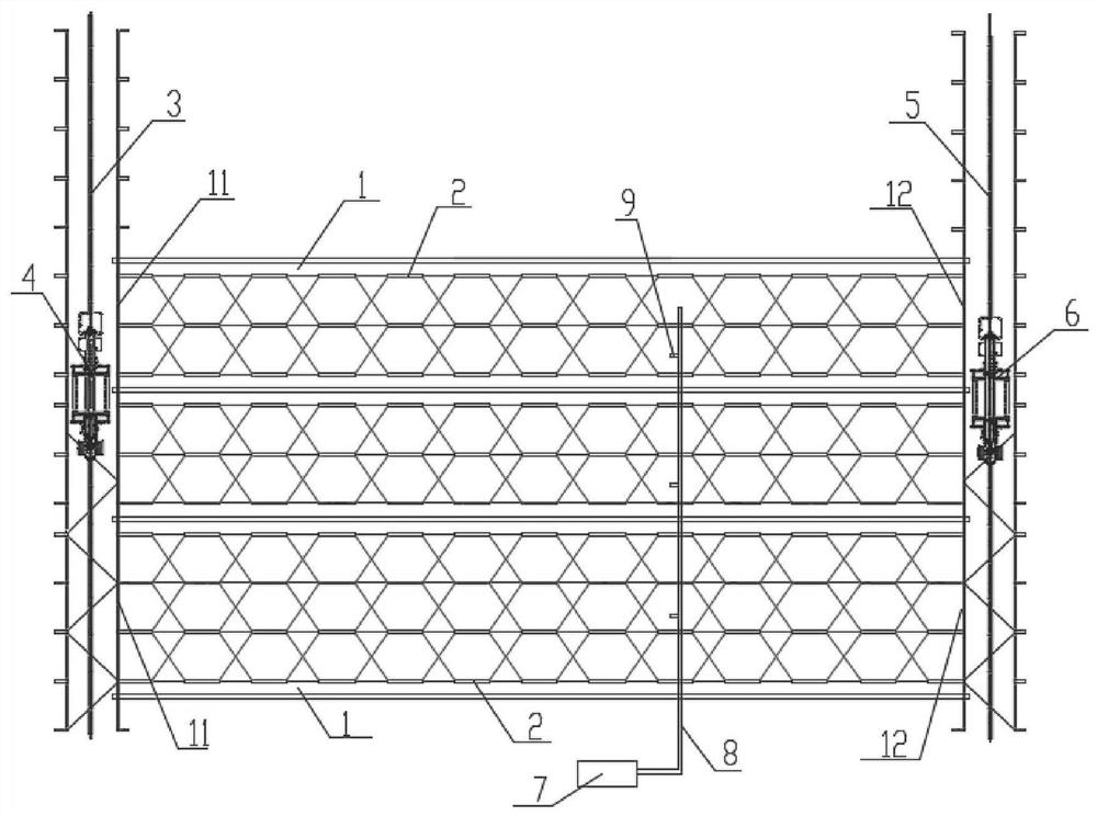
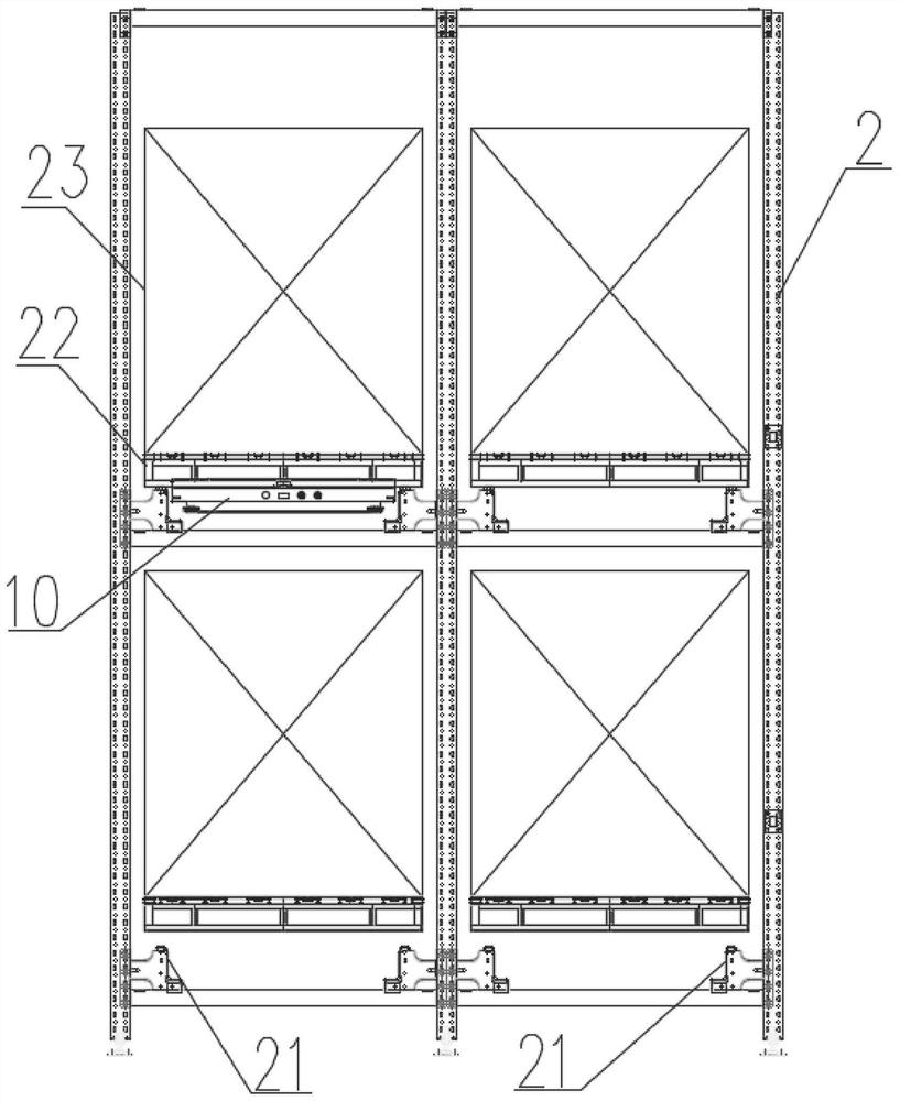
[0016] see figure 1 and figure 2 , using the scheme of three curing rooms 1 for detailed description.

[0017] The steam curing device for prefabricated components includes three curing rooms 1 arranged side by side. The curing rooms 1 are of a closed structure, and the two ends of the curing room 1 are respectively provided with an inlet 11 and an outlet 12 .

[0018] At least two rows of shelves 2 are arranged side by side in the curing room 1, and the shelves 2 are elongated structures. The two ends of the shelves 2 correspond to the entrance 11 and the exit 12 respectively, and the quantity of the entrance 11 and the exit 12 can be set according to the number of rows of the shelves 2. Make sure that a row of shelves 2 corresponds to an entrance 11 and an exit 12, so that the entrance 11, shelves 2 and exit 12 are in a straight line. A set of third rails 21 is provided on the inner bottom of the shelf, and the third rails 21 are provided for the shuttle car 10 to transpo...


PUM


Abstract

The invention discloses a steam curing device for a prefabricated part. The device comprises at least one curing chamber, the curing chamber is of a closed structure, and an inlet is formed in one endof the curing chamber. A goods shelf is arranged in the curing chamber, a first rail is arranged on the outer side of the inlet end of the curing chamber, and a first stacking machine is arranged onthe first rail. The device further comprises a steam generator which is communicated with the interior of the curing chamber through a steam pipeline, and the steam pipeline in the curing chamber is controlled to be opened and closed through a valve. The steam curing device for the prefabricated part solves the problem that a large amount of labor and land are needed in the automatic curing process of a traditional small prefabricated part, dependence on the labor and the land is greatly reduced, and economic benefits are good.

Description

technical field [0001] The invention relates to a maintenance device for prefabricated components, in particular to a steam maintenance device for small prefabricated components used in highway and municipal ramp projects. Background technique [0002] At present, the main mode of maintenance for small prefabricated components is to carry out natural maintenance inside a large factory building. The main steps are to spread the prefabricated components inside the factory building, then carry out natural maintenance, and finally, more than 20 workers manually carry each prefabricated component. This maintenance method requires manual management and safety, environmental protection and other issues are uncontrollable; with the increase in land cost, the maintenance cost of the existing maintenance mode is rapidly increasing, which is no longer suitable for the needs of development. Contents of the invention [0003] The technical problem to be solved by the present invention...

Claims


Application Information

Patent Timeline
IPC IPC(8): B28B11/24
CPCB28B11/245
Inventor 刘培艳刘海鹏
Owner 南通齐鑫电气自动化科技有限公司
Learn More