Large-scale ion beam polisher for optical parts

A technology of optical parts and ion beams, which is applied in the field of ion beam polishing, can solve the problems of affecting the polishing efficiency of ion beam polishing machines, long set-up time, and high resource consumption, and achieves improved operability and convenience, simple structure, and easy work. The effect of clean environment

Active Publication Date: 2014-12-17
NAT UNIV OF DEFENSE TECH
View PDF5 Cites 0 Cited by
  • Summary
  • Abstract
  • Description
  • Claims
  • Application Information

AI Technical Summary

Problems solved by technology

[0005] Existing large-scale ion beam polishing machines have the disadvantages of building a vacuum environment, which consumes a lot of resources and takes a long time. When processing large-diameter optical parts, the impact of this disadvantage is not obvious
However, because the ion beam polishing machine needs to carry out a large number of process experiments on small and medium-caliber optical parts before polishing, and according to the design method of the existing large-scale ion beam polishing machine, in order to complete the process experiments, it is necessary to repeat many times to establish a vacuum environment, so , this shortcoming will cause the total vacuum environment establishment time of the large-scale ion beam polishing machine to be extremely long, waste a lot of resources, and affect the polishing efficiency of the ion beam polishing machine
In addition, when using this ion beam polishing machine to perform ion beam polishing on a large number of small and medium-caliber optical parts, this shortcoming is still very prominent

Method used


Image

  • Large-scale ion beam polisher for optical parts
  • Large-scale ion beam polisher for optical parts
  • Large-scale ion beam polisher for optical parts

Examples


Embodiment Construction

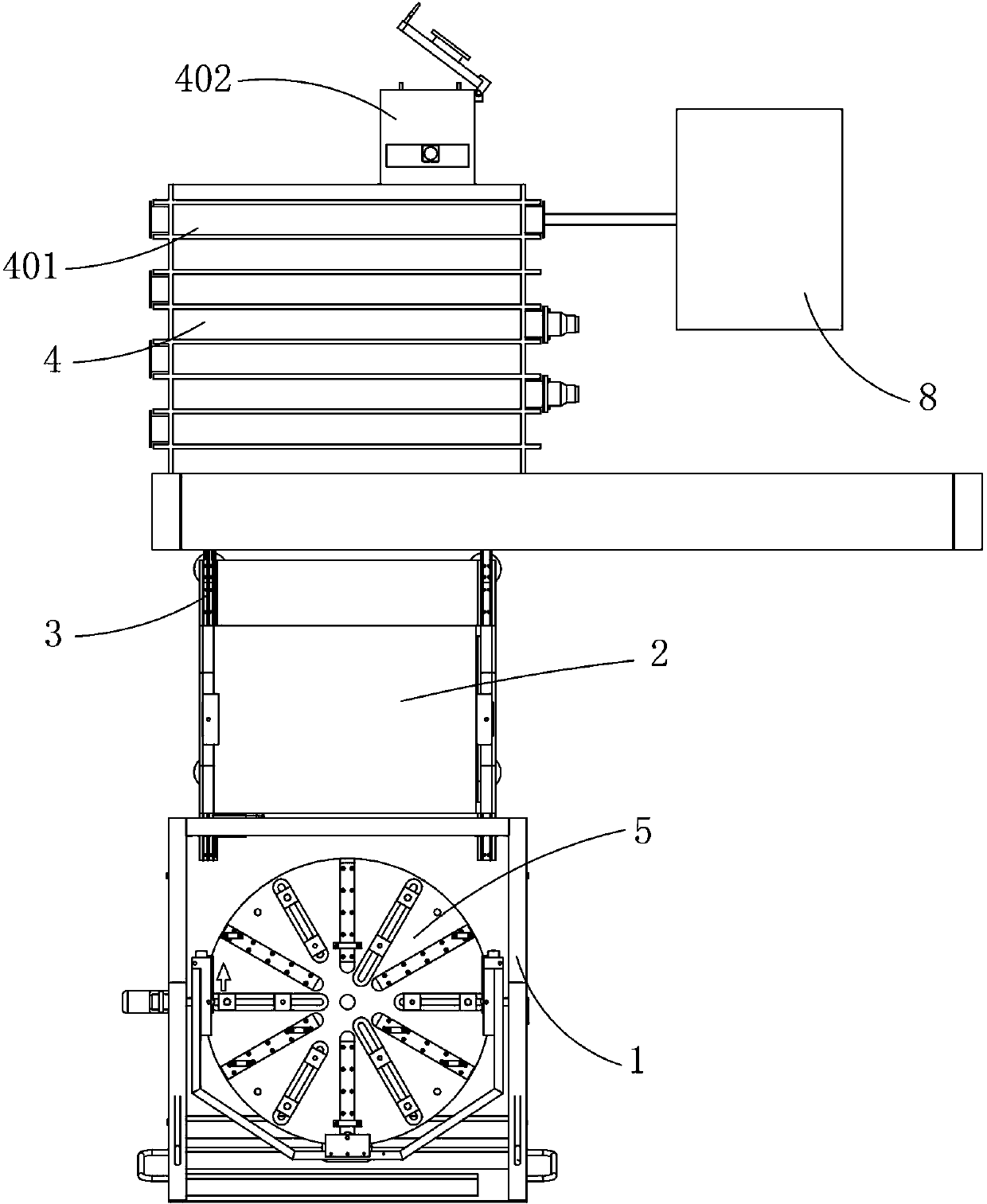
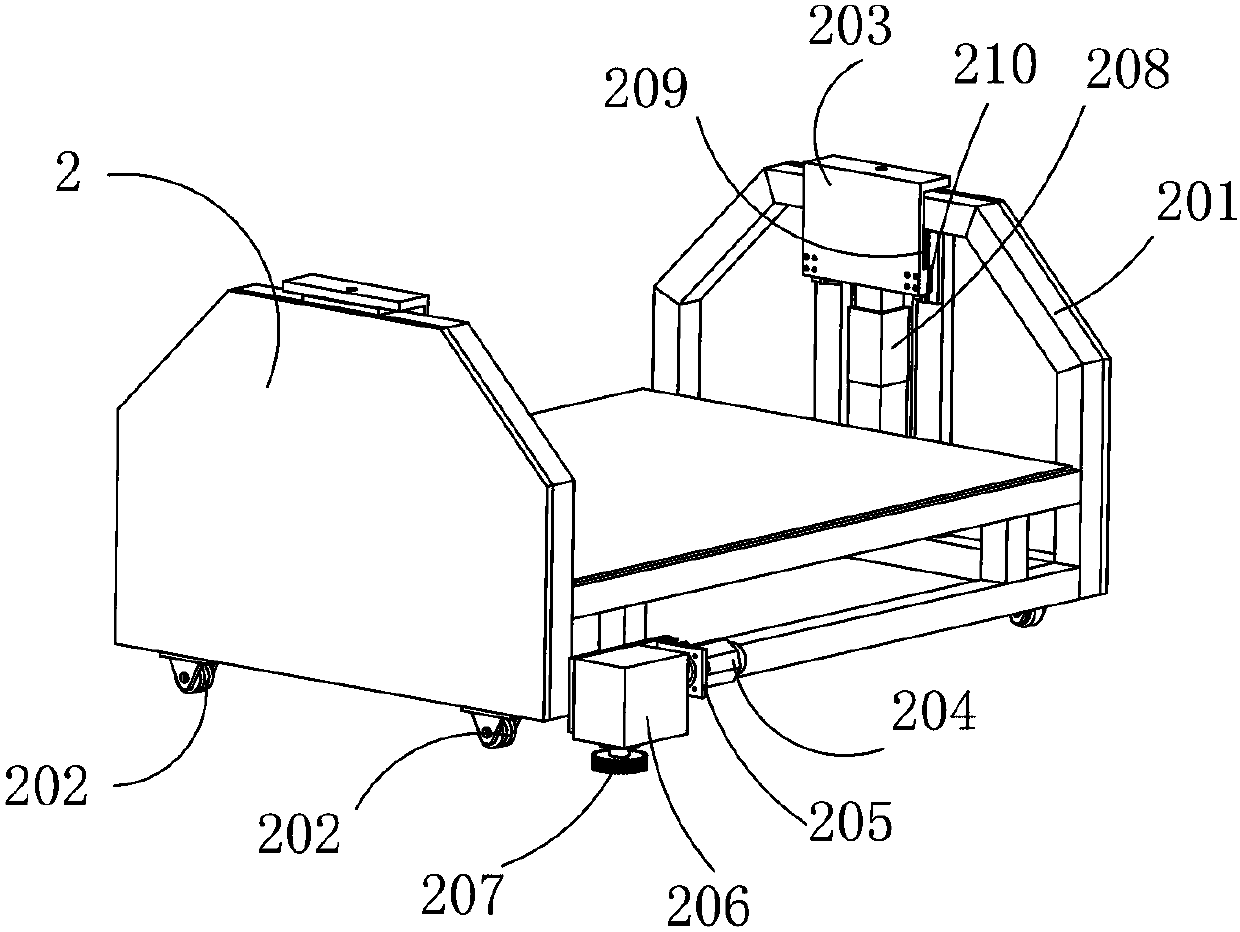
[0033] Figure 1 to Figure 11Shown is a large-scale optical part ion beam polishing machine of the present invention, including a vacuum polishing system 4, a carrying device 3, used for transporting the large-diameter workpiece 6 after measurement, and making the large-diameter workpiece 6 stand The overturning device 1 with the processing surface kept downward, and the conveying device 2 and the carrying device 3 for receiving the large-diameter workpiece 6 conveyed by the overturning device 1 and sending the large-diameter workpiece 6 to the main vacuum chamber 401 of the vacuum polishing system 4 It includes a guide rail 302 and an inner frame 301 arranged in the main vacuum chamber 401 and used to accept the large-diameter workpiece 6 conveyed by the conveying device 2. The conveying device 2 is arranged on the guide rail 302 and moves along the guide rail 302. The vacuum polishing system 4 Connected with a vacuum device 8, the main vacuum chamber 401 can be vacuumed thro...


PUM


Abstract

The invention discloses a large-scale ion beam polisher for optical parts. The large-scale ion beam polisher comprises a vacuum polishing system, a bearing device, a turning device for transporting measured large-caliber workpieces and enabling large-caliber workpiece faces to be machined to be kept downwards in the transportation process and a conveying device for carrying the large-caliber workpieces transported by the turning device and conveying the large-caliber workpieces to a main vacuum chamber of the vacuum polishing system. The bearing device comprises a guide rail and an inner frame arranged in the main vacuum chamber and used for carrying the large-caliber workpieces conveyed by the conveying device. The conveying device is arranged on the guide rail and moves along the guide rail. The large-scale ion beam polisher for the optical part has the advantages of being simple in structure, convenient to operate and control and capable of guaranteeing cleanness of working environment, improving machining precision and efficiency, and being long in service life.

Description

technical field [0001] The invention relates to ion beam polishing technology, in particular to an ion beam polishing machine for large optical parts. Background technique [0002] The ion beam polishing method is a unique and effective processing method in optical mirror processing. Since the physical mechanism of material removal by ion beam polishing is the atomic sputtering effect, the amount of material removal during ion beam polishing can be controlled to the atomic level, and the polishing precision is very high; because the removal function in ion beam polishing is stable and not easy to change, Therefore, ion beam polishing has high certainty and fast surface shape convergence; because ion beam polishing is a non-contact polishing method, there is no contact stress and strain, and the removal function does not change when processing the edge of the workpiece, and there is no edge effect. [0003] Ion beam polishing machine is the basic equipment for ion beam polis...

Claims


Application Information

Patent Timeline
Patent Type & Authority Patents(China)
IPC IPC(8): B24B1/00
Inventor 戴一帆李圣怡解旭辉周林史宝鲁廖文林
Owner NAT UNIV OF DEFENSE TECH
Why Eureka
Try Eureka