a thermal printer

A technology of thermal printers and printers, applied in typewriters, printing devices, printing, etc., can solve the problems of small installation space of printers, small size of thermal label printers, small printers, etc.

Active Publication Date: 2022-05-03
MICROPRINTER INNOVATION TECHSHENZHEN CO LTD
View PDF0 Cites 0 Cited by
  • Summary
  • Abstract
  • Description
  • Claims
  • Application Information

AI Technical Summary

Problems solved by technology

[0003] At present, with the rapid development of technology, the volume of thermal label printers is getting smaller and smaller. When using thermal label printers, the label roll needs to be installed inside the thermal label printer, and then heated at high temperature to make the image printed on the label surface, so as to complete the label printing, but when the existing thermal label printer installs the label, due to the small size of the printer and the small installation space inside the printer, it is not convenient for the staff to quickly install the label , so a thermal printer is needed to solve the problems raised in the above

Method used


Image

  • a thermal printer
  • a thermal printer
  • a thermal printer

Examples


Embodiment Construction

[0024] The following will clearly and completely describe the technical solutions in the embodiments of the present invention with reference to the accompanying drawings in the embodiments of the present invention. Obviously, the described embodiments are only some, not all, embodiments of the present invention. Based on the embodiments of the present invention, all other embodiments obtained by persons of ordinary skill in the art without making creative efforts belong to the protection scope of the present invention.

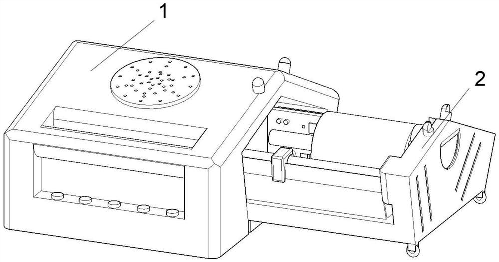
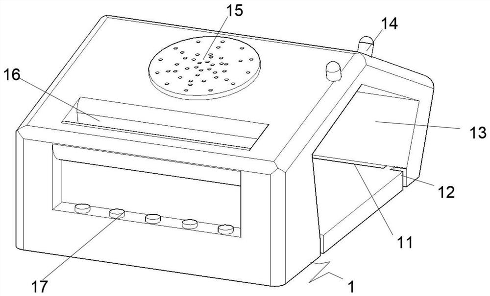
[0025] see Figure 1-6 , an embodiment provided by the present invention: a thermal printer, including a printer case 1 and a receiving device 2, the receiving device 2 is movably plugged into the side of the printer case 1, and the side end surface of the printer case 1 is provided with The first insertion slot 13, the two sides of the inner bottom surface of the first insertion slot 13 are provided with limit slides 11, and the edge of one end face of the fi...


PUM


Abstract

The present invention relates to the technical field of printer equipment, in particular to a thermal printer, comprising a printer casing and a receiving device, the receiving device is movably plugged into the side of the printer casing, and the side end surface of the printer casing is opened There is a first insertion slot, and limit slides are provided on both sides of the inner bottom surface of the first insertion slot, grooves are symmetrically opened on the edge of one end surface of the first insertion slot, and the top of the printer casing An extruding block is movably inserted on the edge of one end of the surface, and a heat dissipation hole is opened in the center of the top surface of the printer casing, and an outlet is opened on the top surface of the printer casing and located at the edge of the heat dissipation hole. An operation panel is fixedly installed on the end surface, a receiving base is fixedly installed inside the receiving device, and a limiting device is installed movable inside the receiving base. The present invention can expand the installation space of the label roll by pulling out the receiving base, which is convenient for workers to install the label roll.

Description

technical field [0001] The invention relates to the technical field of printer equipment, in particular to a thermal printer. Background technique [0002] The working principle of a thermal printer is that a semiconductor heating element is installed on the print head. After the print head is heated and contacts the thermal printing paper, the required pattern can be printed out. The principle is similar to that of a thermal fax machine. It is produced by a chemical reaction in the film, and the chemical reaction of this thermal printer is carried out at a certain temperature. High temperatures accelerate this chemical reaction, and at 200°C, the reaction completes within microseconds. [0003] At present, with the rapid development of technology, the volume of thermal label printers is getting smaller and smaller. When using thermal label printers, the label roll needs to be installed inside the thermal label printer, and then heated at high temperature to make the image ...

Claims


Application Information

Patent Timeline
Patent Type & Authority Patents(China)
IPC IPC(8): B41J2/32B41J3/407B41J15/04
CPCB41J2/32B41J3/4075B41J15/048B41J15/04
Inventor 朱文强杨帆
Owner MICROPRINTER INNOVATION TECHSHENZHEN CO LTD
Why Eureka
Try Eureka