
Micropore pile with inner-wall supporting structure

A support structure and micro-porous technology, which is applied in infrastructure engineering, sheet pile walls, buildings, etc., can solve the problems of unstable support of micro-porous piles, and the lack of support and bearing effect of micro-porous piles, so as to improve the service life. , to prevent position deviation, the effect of reasonable design

Inactive Publication Date: 2019-02-22
SUIZHOU POWER SUPPLY COMPANY STATE GRID HUBEI ELECTRIC POWER +1
View PDF0 Cites 0 Cited by
  • Summary
  • Abstract
  • Description
  • Claims
  • Application Information

AI Technical Summary

Problems solved by technology

[0002] Hole piles are excavated holes manually or mechanically. Manually dug hole piles, engineering term, are reinforced concrete piles that are excavated manually and cast on site. Manually dug hole piles are generally thicker in diameter, and the thinnest is more than 800mm. , can bear the main body of the structure with fewer floors and greater pressure, and is widely used. Artificially dug holes are piles that are made by manually digging holes, then placed steel cages, and poured concrete. For micro holes For piles, its diameter is generally between 10 and 30 cm, and its internal support is very important, but the inner wall of the current micro-hole pile generally does not have the effect of supporting pressure, making the internal support of the micro-hole pile extremely unstable

Method used


Image

  • Micropore pile with inner-wall supporting structure
  • Micropore pile with inner-wall supporting structure
  • Micropore pile with inner-wall supporting structure

Examples


Embodiment Construction

[0017] In order to make the technical means realized by the present invention; creative features; achieve the purpose and effect easy to understand, the present invention will be further elaborated below in conjunction with specific embodiments.

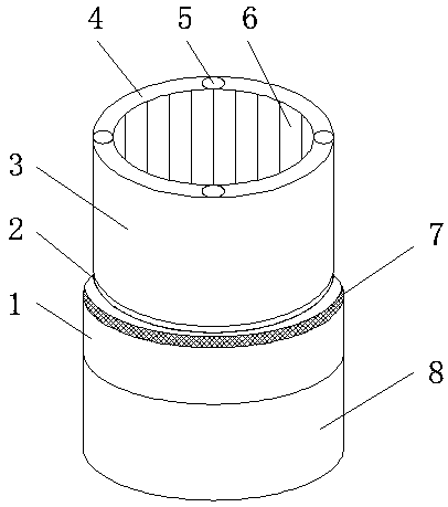
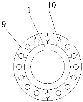
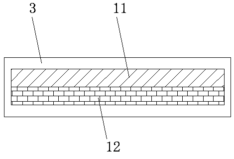
[0018] Such as Figure 1-3 As shown, a microporous pile with an inner wall support structure includes a base 8, the top of the base 8 is fixedly connected with a support bracket 1, and the inside of the support bracket 1 is fixedly connected with a pressure-bearing block 9, and the pressure-bearing A support rod 10 is fixedly connected between the blocks 9, the surface of the support bracket 1 is provided with a protective layer 7, the top of the support bracket 1 has a limiting groove 2, and the top of the supporting bracket 1 is fixed by the limiting groove 2 Connected with a top pile 3, the inside of the top pile 3 is fixedly connected with a steel plate 12, the top of the steel plate 12 is fixedly connected with a concrete layer ...


PUM


Abstract

The invention discloses a micropore pile with an inner-wall supporting structure. The micropore pile with the inner-wall supporting structure comprises a base. A supporting bracket is fixedly connected to the top end of the base. Pressure-bearing blocks are fixedly connected inside the supporting bracket. According to the micropore pile with the inner-wall supporting structure, the design is reasonable, and the use is convenient. The supporting bracket, a protection layer, the pressure-bearing blocks and supporting rods are arranged; the corrosion resistant and rust resistant roles and the like can be effectively played conveniently through the protection layer on the surface of the supporting bracket; the service life of the supporting bracket is prolonged; austenite steel texture is adopted by the pressure-bearing blocks, and the effect of bearing pressure can be effectively produced; the supporting role of a top pile is played through the supporting rods; a limiting groove, locatingrods and a limiting frame are arranged, the top pile can be connected with the supporting bracket in a concave-convex manner through the limiting groove, and the roles of supporting and limiting areeffectively played; the top pile can be fixed and limited through the locating rods and the limiting frame, and positional deviation between the top pile and the supporting bracket is prevented from being generated. The micropore pile with the inner-wall supporting structure is simple, convenient and suitable to be popularized extensively.

Description

technical field [0001] The invention relates to the technical field of hole pile support devices, in particular to a micro hole pile with an inner wall support structure. Background technique [0002] Hole piles are excavated holes manually or mechanically. Manually dug hole piles, engineering term, are reinforced concrete piles that are excavated manually and cast on site. Manually dug hole piles are generally thicker in diameter, and the thinnest is more than 800mm. , can bear the main body of the structure with fewer floors and greater pressure, and is widely used. Artificially dug holes are piles that are made by manually digging holes, then placed steel cages, and poured concrete. For micro holes For piles, its diameter is generally between 10 and 30 cm, and its internal support is very important, but the inner wall of the current micro-hole pile generally does not have the effect of supporting pressure, making the internal support of the micro-hole pile extremely unsta...

Claims


Application Information

Patent Timeline
Patent Type & Authority Applications(China)
IPC IPC(8): E02D5/34E02D5/38
CPCE02D5/34E02D5/38
Inventor 方晴张传义王早桂张迎亚王晓嵩罗先国
Owner SUIZHOU POWER SUPPLY COMPANY STATE GRID HUBEI ELECTRIC POWER
Learn More