Gynecological dilator

A dilator and gynecological technology, applied in the field of dilators, can solve problems such as cleaning, dilator damage, patient injury, etc., and achieve the effect of simple and quick operation, increase friction force, and ensure stability

Inactive Publication Date: 2022-01-04
淄博市中心医院
View PDF0 Cites 0 Cited by
  • Summary
  • Abstract
  • Description
  • Claims
  • Application Information

AI Technical Summary

Problems solved by technology

[0009] The purpose of the present invention is to provide a gynecological dilator to solve the problem that the existing dilator proposed in the above background technology has a simple structure during use and requires medical personnel to manually adjust the size of the dilation range, which increases to a certain extent The labor load of the medical staff, and at the same time, there is often insufficient light during the inspection process, which affects the diagnosis of the medical staff. The existing dilator is not easy to disassemble, and the cleaning and disinfection of the dilator is not thorough, which is easy to bring pain to the patient. To cause secondary damage, the existing dilator cannot be cleaned immediately after use, requiring medical staff to bring the dilator to the interior of the disinfection room to be able to disinfect it, thereby reducing the work of medical staff Efficiency, the existing dilator is inconvenient to place after use, and then when the dilator is placed improperly, it will cause damage to the dilator, seriously affecting its use, and the existing dilator needs to be stored after disinfection , however, the ordinary placement process will still cause a large number of bacteria on the surface of the dilator, which will affect the problem of the next use

Method used


Image

  • Gynecological dilator
  • Gynecological dilator
  • Gynecological dilator

Examples


Embodiment Construction

[0035] The following will clearly and completely describe the technical solutions in the embodiments of the present invention with reference to the accompanying drawings in the embodiments of the present invention. Obviously, the described embodiments are only some, not all, embodiments of the present invention. Based on the embodiments of the present invention, all other embodiments obtained by persons of ordinary skill in the art without making creative efforts belong to the protection scope of the present invention.

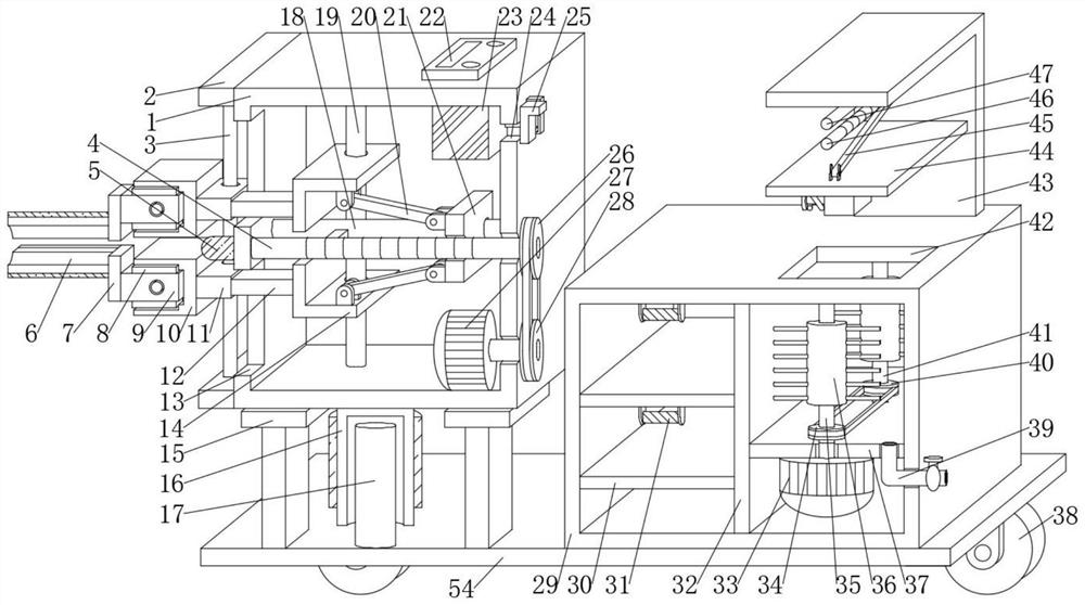
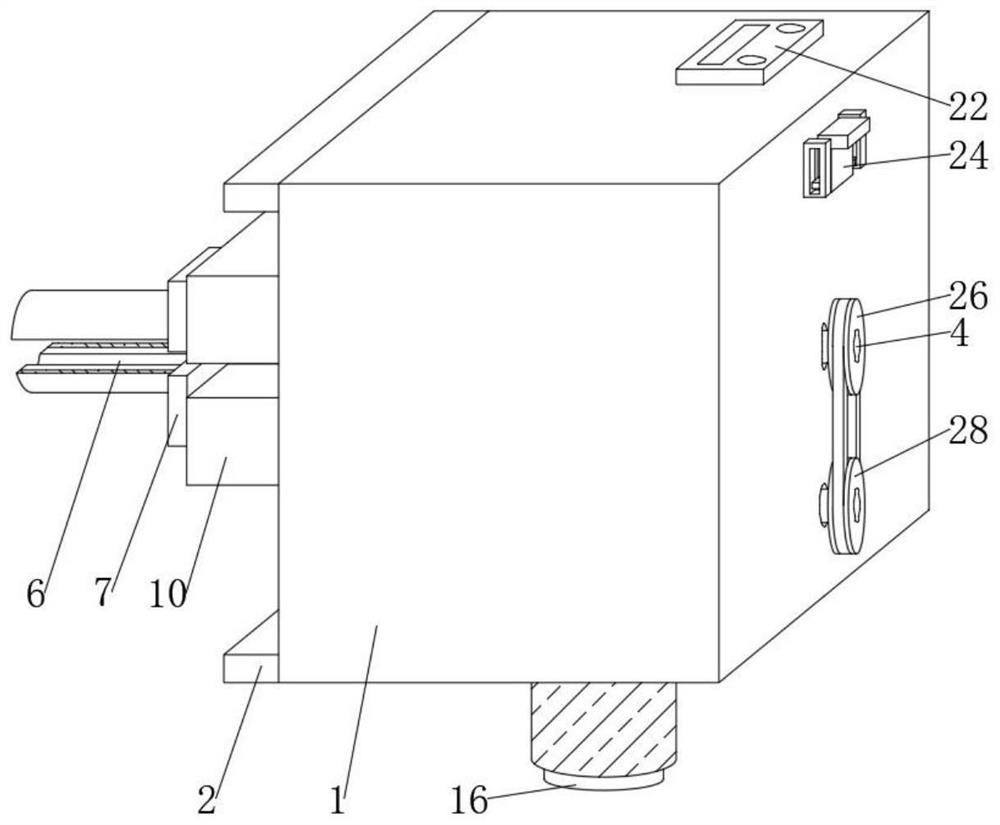
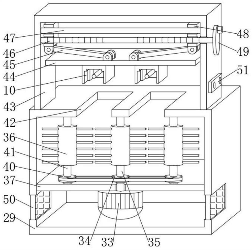
[0036] Such as Figure 1-8As shown, the present invention provides a technical solution: a gynecological dilator, including an expansion adjustment box 1, a motor one 27 is fixedly connected to the inner bottom surface of the expansion adjustment box 1, and the output shaft of the motor one 27 passes through the right side of the expansion adjustment box 1. The side wall is fixedly connected with a sprocket wheel 1 28, and the sprocket wheel 1 28 is transmissi...


PUM


Abstract

The invention discloses a gynecological dilator, which relates to the technical field of medical equipment and comprises a dilation adjusting box, and a first motor is fixedly connected to the inner bottom surface of the dilation adjusting box. Through mutual cooperation of a first motor, a first chain wheel, a second chain wheel, a first threaded rod, a first threaded block, an expansion rod, an L-shaped expansion plate, a connecting column and a movable plate, two fixing mechanisms can be automatically driven to be away from each other, then two arc-shaped expansion pieces can be driven to be away from each other, the effect of expanding the affected part of a patient is achieved, and therefore, medical staff can adjust the size of the expansion range according to actual conditions, meanwhile, in the using process of the device, the affected part of a patient can be illuminated by turning on the arranged light supplementing lamp, then the medical staff can diagnose the patient more accurately, and through the soft cushion layer arranged on the arc-shaped expansion pieces, the dilation part of the patient can be protected in the dilation process of the affected part of the patient.

Description

technical field [0001] The invention relates to a dilator, in particular to a gynecological dilator. Background technique [0002] Gynecology is a diagnosis and treatment subject of medical institutions. Gynecology is a branch of obstetrics and gynecology. It is a professional department that diagnoses and treats female gynecological diseases. It is divided into Western medicine gynecology and Chinese medicine gynecology. Gynecological diseases include: diseases of the female reproductive system are Gynecological diseases, including vulvar diseases, vaginal diseases, uterine diseases, fallopian tube diseases, ovarian diseases, etc. The dilator is a commonly used surgical instrument in the process of gynecological examination. The duckbill-shaped upper expansion plate and the lower expansion plate are opened and closed through the expansion of the dilator, so that it is convenient for medical staff to inspect and treat the affected part of gynecological patients. [0003] At...

Claims


Application Information

Patent Timeline
IPC IPC(8): A61B1/32A61B1/303A61B1/06A61B90/70A61L2/10A61L2/18A61B50/31A61B50/39B08B1/04
CPCA61B1/32A61B1/303A61B1/0661A61B90/70A61L2/10A61L2/18A61B50/31A61B50/39A61B2050/311B08B1/32B08B1/12
Inventor 丁玉梅李玉娇庄士超路明
Owner 淄博市中心医院
Why Eureka
Try Eureka