Binding device and automatic binding robot

A technology for driving parts and driving components, which is applied in the construction, building structure, processing of building materials, etc., can solve the problems of easy deviation, failure, and impact of the end of the tie wire, so as to improve the success rate of lashing and lashing. quality effect

Pending Publication Date: 2021-02-09
CHINA CONSTR SCI & TECH CO LTD
View PDF0 Cites 2 Cited by
  • Summary
  • Abstract
  • Description
  • Claims
  • Application Information

AI Technical Summary

Problems solved by technology

[0005] This application provides a binding device and an automatic binding robot to solve the problem in the related art that when binding

Method used


Image

  • Binding device and automatic binding robot
  • Binding device and automatic binding robot
  • Binding device and automatic binding robot

Examples


Example Embodiment

[0040]In order to make the purpose, technical solutions and advantages of the embodiments of this application clearer, the technical solutions in the embodiments of this application will be described clearly and completely in conjunction with the drawings in the embodiments of this application. Obviously, the described embodiments These are part of the embodiments of this application, not all of the embodiments. Based on the embodiments in this application, all other embodiments obtained by a person of ordinary skill in the art without creative work shall fall within the protection scope of this application.

[0041]In the description of the embodiments of the present application, the terms “first” and “second” are only used for descriptive purposes, and cannot be understood as indicating or implying relative importance or implicitly indicating the number of indicated technical features. Therefore, the features defined with "first" and "second" may explicitly or implicitly include at l...


PUM


Abstract

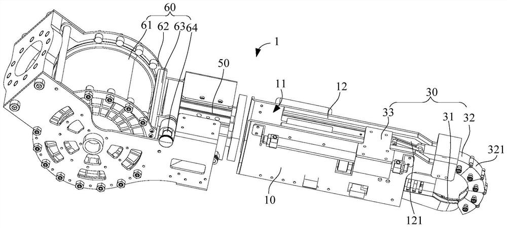
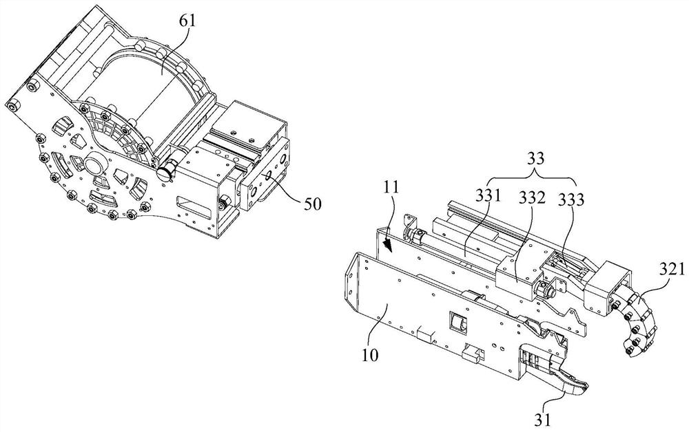
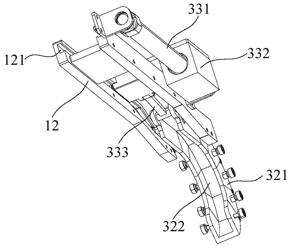
The invention provides a binding device and an automatic binding robot. The binding device comprises an operation arm, a wire feeding mechanism, a wire bending mechanism and a screwing mechanism; thewire feeding mechanism is arranged on an operation arm and used for conveying binding wires to the wire bending mechanism; the wire bending mechanism is arranged at the front end of the operation armand comprises a guide jaw, a first guide part and a first drive assembly; the guide jaw is fixedly connected with the operation arm, the first guide part is movably connected with the operation arm, the first driving assembly is arranged on the operation arm, the first driving assembly is connected with the first guide part and used for driving the first guide part to surround a reinforcing steelbar intersection point so as to form a closed guide loop with the guide jaw, and the closed guide loop is used for guiding the binding wires, so that a binding ring is formed at the steel bar intersection point; the screwing mechanism is arranged on the operation arm and is adjacent to the wire bending mechanism; and the screwing mechanism is used for screwing the two ends of the binding ring so as to bind the steel bar intersection point.

Description

technical field [0001] The present application relates to the technical field of construction equipment, in particular to a binding device and an automatic binding robot. Background technique [0002] In the construction industry, steel bars, steel bars or steel plates are usually used as stress-dispersing components in concrete; usually multiple steel bars are bound or bound into a frame structure, and the frame structure is poured in concrete, so as to enhance the strength of reinforced concrete Tensile or compressive etc. When binding or binding the steel bars, it is usually necessary to bend the binding wire to form a binding ring, and set the binding ring around the cross connection of the steel bars, and use a vise or a binding device to turn the opening of the binding wire into a binding head. The mode of using vise to twist is low in efficiency and labor-intensive. [0003] There is an automatic binding device in the related art, which usually includes a wire feedi...

Claims


Application Information

Patent Timeline
IPC IPC(8): E04G21/12
CPCE04G21/123
Inventor 杨博苏世龙樊则森齐株锐卜磊靳程锐田璐璐
Owner CHINA CONSTR SCI & TECH CO LTD
Why Eureka
Try Eureka