
Device for salvaging blockage in oil pipe by hydraulically delivering steel wires and using method thereof

A steel wire and hydraulic technology, which is applied in the field of plugging devices in hydraulic wire salvage oil pipes, can solve the problems of plug resistance, oil pipe blockage, slow descending speed, etc. Delivering high-efficiency effects

Active Publication Date: 2021-02-09
李达
View PDF10 Cites 2 Cited by
  • Summary
  • Abstract
  • Description
  • Claims
  • Application Information

AI Technical Summary

Problems solved by technology

When using the method of working under pressure, two problems must be solved first: one is the sealing of the annular space of the oil casing, and the other is the blockage problem in the oil pipe
[0005] 1. This kind of plug mainly relies on gravity to descend, and the descending speed is slow. The plugging process depends on the deformation of the expansion rubber tube caused by the downhole oil pressure for anchoring, and it cannot be plugged at the specified depth. For oil wells that require a deep sealing depth, not applicable;
[0006] 2. During the fishing process, due to the oil pressure on the upper part of the plug, resistance will be formed on the plug, resulting in slow upward movement;
[0007] 3. For this kind of plug, the upper part is mainly kept in place by sliding slips, and the effect of sliding slips attached to the inner wall of the oil pipe is not good, and it is easy to move upwards, resulting in the failure of the expansion rubber tube to be squeezed and deformed, which affects the sealing effect;

Method used


Image

  • Device for salvaging blockage in oil pipe by hydraulically delivering steel wires and using method thereof
  • Device for salvaging blockage in oil pipe by hydraulically delivering steel wires and using method thereof
  • Device for salvaging blockage in oil pipe by hydraulically delivering steel wires and using method thereof

Examples


Embodiment Construction

[0036]The specific content of the present invention will be described in detail below in conjunction with the accompanying drawings and specific embodiments.

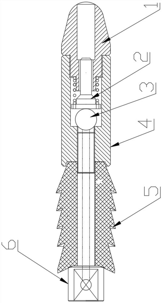
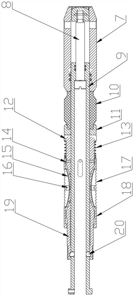
[0037] Such as figure 1 As shown in Fig. 1, a plugging device in a hydraulic feeding wire salvage oil pipe, including a guide mechanism, a seat seal mechanism, and a salvage mechanism,

[0038] Such as figure 2 As shown, the guide mechanism includes a guide head 1, a valve core 2, a ball 3, a valve body 4, a rubber tower 5, and a rubber tower shaft 6; the guide head 1 is conical, and a through hole is provided in the center to guide The valve body 4 is detachably connected to the rear of the head 1; the valve body 4 is cylindrical, and the center runs through, and a cavity is formed between the valve body 4 and the guide head 1, and a ball 3 and a valve core 2 are installed in the cavity , the spool 2 is a rotary part with a T-shaped cross-section, the ball 3 withstands the through hole at the rear end of the valve b...


PUM


Abstract

The invention discloses a device for salvaging blockage in an oil pipe by hydraulically delivering steel wires and a using method thereof. The plug device comprises a guide mechanism, a setting mechanism and a fishing mechanism; the guide mechanism comprises a guide head, a valve core, a valve ball, a valve body, a rubber tower and a rubber tower shaft; the guide head is a cone; the rubber tower is made of cylindrical rubber; a plurality of circles of one-way sawtooth-shaped rubber rings are arranged at the outer side of the rubber tower; the setting mechanism comprises an inclined pusher, a sealing shaft, a central shaft, a rubber sleeve, a gland, a lower taper sleeve, a limiting spring plate spring, a slip, a slip sheath, an upper taper sleeve and a stop block; the inclined pusher, the rubber sleeve, the gland, the lower taper sleeve, the slip, the slip sheath and the upper taper sleeve are sequentially sleeved on the central shaft from front to back; the fishing mechanism comprisesa fixing sleeve, a pin shaft, a shear pin, a pawl, a torsional spring, a limiting shaft and a fishing connector; the pawl is installed in the middle of the limiting shaft through the pin shaft; and the front portion of the fishing connector is connected with the pin shaft. The device for salvaging the blockage in the oil pipe by hydraulically delivering the steel wires and the using method thereofare higher in delivery efficiency, high in setting stability and easy to implement.

Description

technical field [0001] The invention belongs to the field of blowout prevention and plugging in high-pressure oil pipes, and in particular relates to a plugging device for salvaging oil pipes by hydraulic feeding steel wires and a use method thereof. Background technique [0002] When oil wells or water injection wells are used for downhole operations, if there is pressure downhole, it is usually necessary to kill the well or blow out to reduce the pressure. For killing operations, the specific gravity of the killing fluid is very important during the operation. If the specific gravity of the killing fluid is small, it is impossible to kill the well, and there is a hidden danger of blowout; if the specific gravity of the killing fluid is large, it will seep into the formation along the pores or fractures, block the gas flow channel, pollute the production layer near the bottom of the well, affect the permeability of the formation, and eventually cause production decline. Re...

Claims


Application Information

Patent Timeline
Patent Type & Authority Applications(China)
IPC IPC(8): E21B33/126E21B33/1295E21B33/06E21B31/12E21B34/00
CPCE21B33/1265E21B33/1295E21B33/06E21B31/12E21B34/00
Inventor 李达
Owner 李达
Learn More