
Distribution valve, pumping system and pumping machine

A pumping system and distribution valve technology, which is applied in the field of distribution valves, pumping systems and pumping machinery, can solve the problem of long reversing time, reversing noise, reversing resistance, reversing impact and large reversing wear, S tube Issues such as dispensing valves not working efficiently

Active Publication Date: 2021-02-09
SANY AUTOMOBILE MFG CO LTD
View PDF8 Cites 0 Cited by
  • Summary
  • Abstract
  • Description
  • Claims
  • Application Information

AI Technical Summary

Problems solved by technology

However, the S-pipe distributing valve is hydraulically driven, which makes the reversing noise, reversing resistance, reversing impact and reversing wear large, and the reversing time is long. The S-pipe distributing valve cannot work stably and efficiently in the pumping operation. At the same time, it cannot meet the requirements of noise reduction

Method used


Image

  • Distribution valve, pumping system and pumping machine
  • Distribution valve, pumping system and pumping machine
  • Distribution valve, pumping system and pumping machine

Examples


Embodiment 1

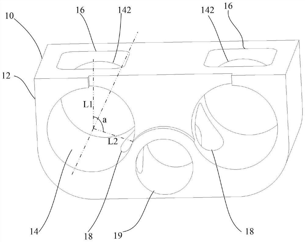
[0055] Specifically, such as figure 1 As shown, in the first implementation of the present invention, the feed port 16 and the discharge port 18 are arranged along the radial extension of the valve hole 14, and the feed port 16 and the discharge port 18 have an included angle a, and the included angle a is equal to 120°.

[0056] In the above setting, the feed port 16 and the discharge port 18 are arranged according to the above angle, so that the valve core 20 only needs to rotate 120° to realize the reversing function of the distribution valve 100, thereby ensuring that the distribution valve 100 can be used in the pumping operation. It can work stably and efficiently while meeting the requirements of the noise reduction method. Further, the application range of the distribution valve 100 is expanded.

[0057] It should be noted that, usually, when the valve core 20 is initially installed into the valve body 10, the first flow channel port 242 of the valve core 20 is aligne...

Embodiment 2

[0065] Embodiment two has following difference with embodiment one:

[0066] Specifically, such as Figure 4 As shown, in the second embodiment of the present invention, the feed port 16 and the discharge port 18 are arranged along the radial extension of the valve hole 14, and the feed port 16 and the discharge port 18 have an included angle a, and the included angle a is equal to 180°.

[0067] In the above arrangement, the feed port 16 and the discharge port 18 are arranged according to the above angles, and the reversing function of the distributing valve 100 can be realized only by rotating 180°. In addition, the included angle a is set to 180°, so that the spool 20 can rotate 360° in one direction, that is, rotate 360° clockwise or counterclockwise, so that the two reversing functions of the dispensing valve 100 can be realized, without the need for As in the first one, it is necessary to reciprocate the spool 20 to realize the two reversing of the distribution valve 10...


PUM


Abstract

The invention provides a distribution valve, a pumping system and a pumping machine. A valve body of the distribution valve comprises a valve body, two valve holes, two feeding ports and two discharging ports, wherein the two valve holes are formed in the valve body side by side, and a feeding and discharging port is formed in one end of each valve hole; the two feeding ports are formed in the valve body and communicate with the two valve holes respectively; and the two discharging ports are formed in the valve body and communicate with the two valve holes respectively. According to the technical scheme, the feeding and discharging ports communicate with the feeding ports or the discharging ports by rotating a valve element, so that the reversing function of the distribution valve can be realized, the distribution valve can work stably and efficiently in pumping operation, the requirement for noise reduction is met, and the application range of the distribution valve is enlarged.

Description

technical field [0001] The invention relates to the technical field of reversing distribution equipment of a pumping system, in particular to a distribution valve, a pumping system and a pumping machine. Background technique [0002] At present, the distribution valve used in the concrete pumping system is a mature S-pipe distribution valve. The S-pipe is hydraulically driven to complete the rapid reversing of the concrete pumping system to achieve continuous pumping operations. However, the S-pipe distributing valve is hydraulically driven, which makes the reversing noise, reversing resistance, reversing impact and reversing wear large, and the reversing time is long. The S-pipe distributing valve cannot work stably and efficiently in the pumping operation. At the same time, the requirements for noise reduction cannot be met. Contents of the invention [0003] The present invention aims to solve at least one of the technical problems existing in the prior art or related ...

Claims


Application Information

Patent Timeline
IPC IPC(8): F04B53/10F04B15/02
CPCF04B53/10F04B15/02
Inventor 朱咸磊雷新军樊毅
Owner SANY AUTOMOBILE MFG CO LTD
Learn More