Flexible electronic device winding detection equipment and detection method thereof

A technology of testing equipment and electronic rolls, which is applied to the components of electrical measuring instruments, measuring electronics, and measuring devices. It can solve the problems of uneven winding on the surface of flexible electronics, slow detection speed, and low efficiency. The effect of smooth winding and feeding, improving winding efficiency and reducing inspection cost

Inactive Publication Date: 2021-02-09
柳少燕
View PDF0 Cites 2 Cited by
  • Summary
  • Abstract
  • Description
  • Claims
  • Application Information

AI Technical Summary

Problems solved by technology

[0003] In the existing flexible electronic winding inspection, the staff usually drives the flexible electronic to wind up on the winding roller manually, and then detects the electrical properties of the flexible electronic after the winding is completed. Not only the detection speed is slow and the efficiency is low, but also the manual winding Moving flexible electronics can easily make the surface of flexible electronics uneven, which not only affects the detection of electronic winding, but also easily damages the flexible electronic body during the detection process, resulting in high cost of flexible electronic detection. Therefore, a flexible electronic winding is needed. Testing Equipment

Method used


Image

  • Flexible electronic device winding detection equipment and detection method thereof
  • Flexible electronic device winding detection equipment and detection method thereof
  • Flexible electronic device winding detection equipment and detection method thereof

Examples


Embodiment Construction

[0029] The following will clearly and completely describe the technical solutions in the embodiments of the present invention with reference to the accompanying drawings in the embodiments of the present invention. Obviously, the described embodiments are only some, not all, embodiments of the present invention. Based on the embodiments of the present invention, all other embodiments obtained by persons of ordinary skill in the art without making creative efforts belong to the protection scope of the present invention.

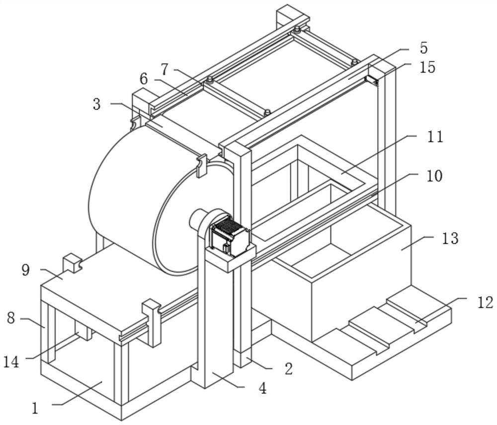
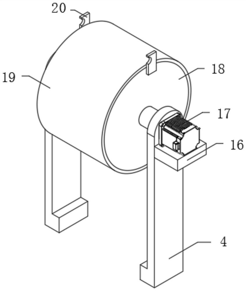
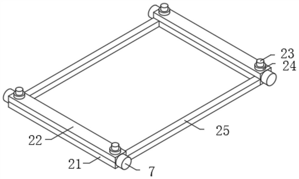
[0030] The present invention provides such Figure 1-5 The shown flexible electronic winding detection device and its detection method include a workbench 1, one end on both sides of the workbench 1 and the middle positions on both sides of the workbench 1 are fixed with a first support frame 2, four fourth One end on the top of a support frame 2 is fixedly provided with a positioning rod 5, and one end on the top of the four first support frames 2 is fixedly ...


PUM


Abstract

The invention discloses flexible electronic device winding detection equipment and detection method thereof. The detection equipment comprises a workbench, first supporting frames are fixedly arrangedat ends of the two sides of the workbench and the middle positions of the two sides of the workbench correspondingly, and positioning rods are fixedly arranged at ends of the tops of the four first supporting frames correspondingly; the ends of the tops of the four first supporting frames are fixedly connected with the two ends of sides of two positioning rods correspondingly, and first sliding grooves are formed in the middles of the other sides of the two positioning rods correspondingly. According to the flexible electronic winding detection equipment, the equipment is fixed through two second pressing plates and positioning strips and positioning rings fixed to the top ends of first pressing plates, a flexible electronic device is wound on a winding roller and the outer wall of a pressure-bearing induction sleeve, so that the winding detection of the flexible electronic device is carried out, the winding detection speed is increased, the detection efficiency is high, the flexibleelectronic device is smooth during detection, a flexible electronic body is prevented from being damaged due to uneven pressure bearing, and the detection cost of the flexible electronic device is reduced.

Description

technical field [0001] The invention relates to the field of flexible electronic winding detection equipment and a detection method thereof, in particular to a flexible electronic winding detection equipment and a detection method thereof. Background technique [0002] Flexible electronics is a general term for a technology. It is an emerging electronic technology that makes organic and inorganic material electronic devices on flexible and ductile substrates. Compared with traditional electronics, flexible electronics has greater flexibility and can adapt to a certain extent. Different working environments meet the deformation requirements of the equipment, and the stretchability and bendability of flexible electronics without damaging their own electronic properties pose new challenges and requirements for the materials used to make circuits. Therefore, flexible electronics needs to be wound up. Perform multiple tests. [0003] In the existing flexible electronic winding i...

Claims


Application Information

Patent Timeline
IPC IPC(8): G01R31/01G01R1/04
CPCG01R1/0425G01R31/01
Inventor 柳少燕
Owner 柳少燕
Why Eureka
Try Eureka