Sound source position determination method and device, readable storage medium and electronic equipment
A technology of sound source location and determination method, which is applied in measurement devices, positioning, radio wave measurement systems, etc., can solve the problem of reducing the accuracy of vehicle sound area detection, and achieve the effect of improving accuracy
Pending Publication Date: 2021-02-09
NANJING HORIZON ROBOTICS TECH CO LTD
0 Cites 1 Cited by
AI-Extracted Technical Summary
Problems solved by technology
For example, when the vehicle is driving, the occupants of the vehicle wake up the equipment in the vehicle by voice, but the vehicle is affected by tire noise, wind...
Method used
In order to improve the accuracy of sound zone detection, k in the formula (14) selects the frequency point that the occurrence probability of sound source signal is larger according to certain criteria, which can reduce the impact of noise interference on the sound zone detection result.
The present embodiment carries out amplitude normalization to absolute transfer function, has guaranteed that the energy that each sound source receives relative microphone is consistent, carries out frequency domain conversion again after amplitude normalization, has reduced amplitude change to transfer function Due to the influence of the matrix, because this embodiment makes the energy received by each sound source consistent with the microphone, the comprehensiveness of sound source localization and the accuracy of localization of each sound source are improved.
The sound source location determination method that the present disclosure proposes has adopted maximum likelihood sound region detection strategy, when solving maximum likelihood function, uses measured model to replace free-field model, can effectively promote the accuracy of sound region detection; This method Avoid the impact of the difference in the amplitude of the measured transfer function; and there are fewer detection targets in the sound area of the vehicle scene, avoiding the problem of the multi-sound source maximum likelihood algorithm, the calculation amount increases exponentially with the number of sound sources, and has high practicality sex.
The sound source position determination device that the above-mentioned embodiment of the present disclosure provides, by adopting maximum likelihood method to carr...
Abstract
The embodiment of the invention discloses a sound source position determination method and device, a readable storage medium and electronic equipment, and the method comprises the steps: carrying outthe modeling of respective transfer functions based on a plurality of positions in a set space, and obtaining transfer function matrixes corresponding to the plurality of positions in the set space; collecting a sound signal emitted by at least one position in the plurality of positions; and processing the sound signal by adopting a maximum likelihood method in combination with the transfer function matrix, and determining the position of a sound source emitting the sound signal in the plurality of positions. According to the embodiment of the invention, the maximum likelihood method is adopted to carry out the sound area detection, so that the influence of the offline modeling amplitude error on the sound area detection result can be avoided; and the ideal transfer function in the maximumlikelihood function is replaced by the modeling transfer function, so that the detection accuracy of the sound zone is improved.
Application Domain
Position fixation
Technology Topic
EngineeringSound source location +3
Image
Examples
- Experimental program(1)
Example Embodiment
[0028]Hereinafter, exemplary embodiments according to the present disclosure will be described in detail with reference to the accompanying drawings. Obviously, the described embodiments are only a part of the embodiments of the present disclosure, rather than all the embodiments of the present disclosure, and it should be understood that the present disclosure is not limited by the exemplary embodiments described herein.
[0029]It should be noted that unless specifically stated otherwise, the relative arrangement of components and steps, numerical expressions and numerical values set forth in these embodiments do not limit the scope of the present disclosure.
[0030]Those skilled in the art can understand that terms such as “first” and “second” in the embodiments of the present disclosure are only used to distinguish different steps, devices, or modules, etc., and do not represent any specific technical meaning, nor does it mean that they are between them. The necessary logical order.
[0031]It should also be understood that in the embodiments of the present disclosure, "plurality" may refer to two or more than two, and "at least one" may refer to one, two, or more than two.
[0032]It should also be understood that any component, data, or structure mentioned in the embodiments of the present disclosure can generally be understood as one or more unless it is clearly defined or the context gives opposite enlightenment.
[0033]In addition, the term "and/or" in the present disclosure is merely an association relationship describing associated objects, indicating that there can be three types of relationships, for example, A and/or B, which can mean that A alone exists, and both A and B exist. , There are three cases of B alone. In addition, the character "/" in the present disclosure generally indicates that the associated objects before and after are in an "or" relationship.
[0034]It should also be understood that the description of the various embodiments of the present disclosure emphasizes the differences between the various embodiments, and the same or similarities can be referred to each other, and for the sake of brevity, the details are not repeated one by one.
[0035]At the same time, it should be understood that, for ease of description, the sizes of the various parts shown in the drawings are not drawn according to actual proportional relationships.
[0036]The following description of at least one exemplary embodiment is actually only illustrative, and in no way serves as any limitation to the present disclosure and its application or use.
[0037]The technologies, methods, and equipment known to those of ordinary skill in the relevant fields may not be discussed in detail, but where appropriate, the technologies, methods, and equipment should be regarded as part of the specification.
[0038]It should be noted that similar reference numerals and letters indicate similar items in the following drawings, so once an item is defined in one drawing, it does not need to be further discussed in the subsequent drawings.
[0039]The embodiments of the present disclosure can be applied to electronic devices such as terminal devices, computer systems, servers, etc., which can operate with many other general-purpose or special-purpose computing system environments or configurations. Examples of well-known terminal devices, computing systems, environments and/or configurations suitable for use with electronic devices such as terminal devices, computer systems, servers, etc. include, but are not limited to: personal computer systems, server computer systems, thin clients, thick clients Computers, handheld or laptop devices, microprocessor-based systems, set-top boxes, programmable consumer electronics, network personal computers, small computer systems, large computer systems, and distributed cloud computing technology environments including any of the above systems, etc.
[0040]Electronic devices such as terminal devices, computer systems, servers, etc. may be described in the general context of computer system executable instructions (such as program modules) executed by the computer system. Generally, program modules may include routines, programs, object programs, components, logic, data structures, etc., which perform specific tasks or implement specific abstract data types. The computer system/server can be implemented in a distributed cloud computing environment. In the distributed cloud computing environment, tasks are executed by remote processing equipment linked through a communication network. In a distributed cloud computing environment, program modules may be located on storage media of local or remote computing systems including storage devices.
[0041]Application overview
[0042]In the process of implementing the present disclosure, the inventor found that when multiple users in the car wake up the voice system in the car, the prior art is usually based on the free-field model and uses the beamforming algorithm in the car for sound zone detection; Some technologies have at least the following problems: due to the complex acoustic environment in the car, the reflection and scattering are relatively strong, the free-field model is different from the actual sound source model, and the accuracy of sound zone detection is poor.
[0043]Exemplary system
[0044]In the prior art, in order to determine the sound source position in multiple positions, the following process is used. The frequency domain signal X(k) received by the microphone array can be expressed by formula (1):
[0045]X(k)=A(k)S(k)+N(k) Formula (1)
[0046]Among them, k is the frequency index, and A(k), S(k) and N(k) are expressed as M×Q-dimensional steering matrix, Q×1-dimensional complex sound source signal and noise signal received by M×1-dimensional microphone, respectively , A(k) is the ideal transfer function (that is, the free field transfer function), and N(k) is the noise signal, which can be expressed by the following formulas (2-5):
[0047]X(k)=[X1(k) X2(k)… XM(k))T Formula (2)
[0048]A(k)=[a1(k) a2(k)… aQ(k)) Formula (3)
[0049]S(k)=[S1(k) S2(k)… SQ(k))T Formula (4)
[0050]N(k)=[N1(k) N2(k)… NM(k))T Formula (5)
[0051]Among them, a in the above formula (3)q(k) can be expressed as the following formula (6):
[0052]
[0053]In the above formulas, []TRepresents the transposition of the matrix, M represents the number of microphones, Q is the number of sound sources, and M>Q (that is, the number of microphones is greater than the number of sound sources). The noise signal N(k) can be assumed to have a mean value of 0 and a covariance matrix of σ2Complex Gaussian noise of I, σ2Is an unknown constant, and I is the identity matrix (a matrix whose value is 1).
[0054]The direction of the sound source in the above formula (1) = [θ1 θ2 … ΘQ]T, Signal S=[S(1)T S(2)T … S(K)T]TAnd σ2Is certain and unknown, K is the maximum frequency index. Ω=[ΘT ST σ2]TThe likelihood function of can be expressed by the following formula (7):
[0055]
[0056]Maximize the likelihood function provided by formula (7) to obtain the sound zone detection result, which can be expressed as the following formula (8):
[0057]
[0058]among them, Represents the pseudo-inverse, that is, in formula (8) It can be expressed by the following formula (9):
[0059]
[0060]among them,()HRepresents conjugate transpose.
[0061]The processes of the above formulas (1) to (9) belong to the method of determining the position of the sound source in the prior art.
[0062]The main idea of the embodiments of the present disclosure is to replace the ideal transfer function with the measured transfer function to more accurately locate the sound source position.
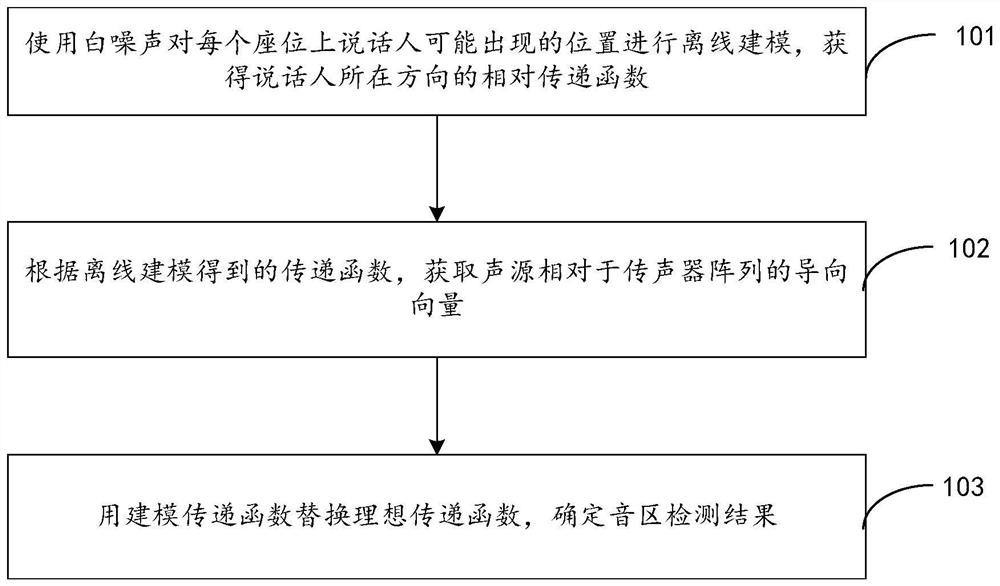
[0063]figure 1 It is a schematic flow chart of a method for determining the position of a sound source provided by an exemplary embodiment of the present disclosure. The method for determining the sound source position provided in this embodiment can be applied to a scene in a set space such as a vehicle-mounted scene. This embodiment takes the application in a vehicle-mounted scene as an example, and includes the following steps:
[0064]Step 101: Use white noise to perform offline modeling of the possible position of the speaker on each seat to obtain the relative transfer function of the speaker's direction.
[0065]Specifically, select a seat q in the car, select P positions in a small area where the speaker may appear on the seat q, and use an artificial mouth (an artificial sound source playback device) in each of the P positions Play white noise, synchronously collect the white noise signal played by the artificial mouth And the signal received by the microphone array x=[x1 x2 … XM], where M is the number of microphones, and the absolute transfer function between the sound source of the qth seat and the mth microphone can be expressed by the following formula (10):
[0066]
[0067]among them, Indicates the time domain signal received by the m-th microphone when the sound source is at the p-th position; N represents the length of the time-domain modeling data, and "*" represents the convolution multiplication.
[0068]For Q seats and M microphone units in the car, offline modeling can determine the transfer function matrix h, which can be expressed by the following formula (11):
[0069]
[0070]Step 102: According to the transfer function h obtained by offline modelingmq , Get the steering vector of the sound source relative to the microphone array, and model the transfer function hmq Perform normalization, which can be expressed by the following formula (12):
[0071]
[0072]Where || ||lRepresents the l norm. When l=1, it means normalization according to amplitude, and when l=2 means normalization according to energy. Transform the normalized transfer function to the frequency domain to obtain the sound source's steering vector relative to the microphone array. At this time, the transfer function matrix H(k) at the k-th frequency can be expressed as Equation (13):
[0073]
[0074]Step 103: Replace the ideal transfer function with the modeling transfer function to determine the sound zone detection result; that is, replace A(k) in formula (8) with H(k). At this time, the sound zone detection result formula (8 ) Can be expressed as the following formula (14):
[0075]
[0076]It can be seen from formula (14) that, assuming that there is an amplitude error in H(k) modeling, as shown in formula (15):
[0077]H(k)=αHreal (k) Formula (15)
[0078]Where Hreal (k) is the true transfer function, and α is a non-zero constant. At this time, in formula (14) It can be expressed as the formula (16):
[0079]
[0080]at this time,
[0081]Among them, due to α and The multiplication cancels each other out. Therefore, the value of α does not affect the result in formula (17). Therefore, it can be seen that the amplitude error of offline modeling has no effect on the sound zone detection result.
[0082]In order to improve the accuracy of sound zone detection, k in formula (14) selects the frequency points with a greater probability of sound source signal according to certain criteria, which can reduce the influence of noise interference on the sound zone detection result.
[0083]Commonly used multi-sound source maximum likelihood sound source sound zone detection algorithm, as the number of sound sources increases, the amount of calculation increases exponentially. The maximum number of sound sources in a car scene is the number of seats in the car. Assuming that the number of seats in the car is Q, the number of sound areas that need to be detected is P. Formula (14) only needs to be calculated Once, you can get the multi-sound source sound zone detection result.
[0084]The sound source location determination method proposed in the present disclosure adopts the maximum likelihood sound zone detection strategy. When solving the maximum likelihood function, the measured model is used to replace the free field model, which can effectively improve the accuracy of sound zone detection; this method avoids the actual measurement The impact of the difference in the amplitude of the transfer function; and there are fewer detection targets in the sound area of the vehicle scene, avoiding the multi-sound source maximum likelihood algorithm, and the problem that the amount of calculation increases exponentially with the number of sound sources, which has high practicability.
[0085]Exemplary method
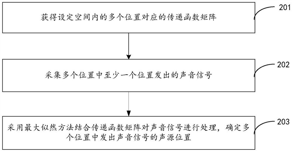
[0086]figure 2 It is a schematic flow chart of a method for determining the position of a sound source provided by another exemplary embodiment of the present disclosure. This embodiment can be applied to electronic equipment, such asfigure 2 As shown, including the following steps:
[0087]Step 201: Obtain transfer function matrices corresponding to multiple positions in a setting space.
[0088]Among them, the setting space can be a space with boundaries such as a vehicle, a conference room, etc., and multiple locations are set in the setting space. For example, when applied to a vehicle (vehicle scene), the multiple locations can be multiple seats in the vehicle .
[0089]Step 202: Collect a sound signal emitted from at least one of the multiple positions.
[0090]Optionally, the sound signal of at least one position may be obtained through a sound collection device such as a microphone.
[0091]Step 203: Use the maximum likelihood method in combination with the transfer function matrix to process the sound signal, and determine the position of the sound source emitting the sound signal among the multiple positions.
[0092]Among them, the maximum likelihood method does not estimate the probability of all positions in this embodiment, but only obtains the most likely position. This embodiment replaces the ideal transfer function in the maximum likelihood function with the transfer function matrix, which improves the estimation Accuracy; optionally, the maximum likelihood function after replacement in this embodiment can refer tofigure 1 Equation (14) in the illustrated embodiment.
[0093]The sound source location determination method provided by the above-mentioned embodiments of the present disclosure adopts the maximum likelihood method for sound zone detection, which can avoid the influence of the offline modeling amplitude error on the sound zone detection result; and replace the maximum likelihood function by the modeling transfer function The ideal transfer function in, improve the accuracy of sound zone detection.
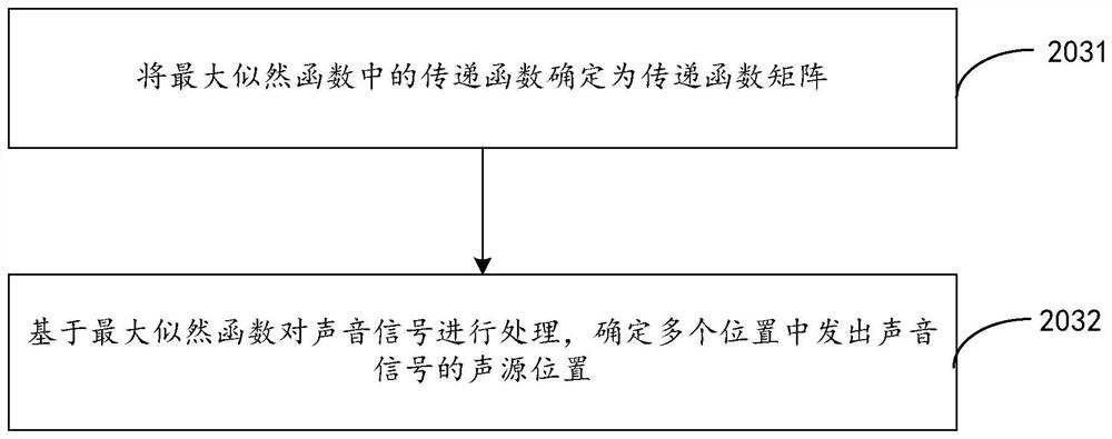
[0094]Such asimage 3 Shown in the abovefigure 2 Based on the illustrated embodiment, step 203 may include the following steps:
[0095]Step 2031: Determine the transfer function in the maximum likelihood function as the transfer function matrix.
[0096]Step 2032: Process the sound signal based on the maximum likelihood function, and determine the position of the sound source emitting the sound signal among the multiple positions.
[0097]The original maximum likelihood function formula is shown in the above formula (8), where A(k) is the ideal transfer function. In this embodiment, A(k) is replaced by the transfer function matrix H(k). At this time, The formula (8) of the sound zone detection result can be expressed as the abovefigure 1 Formula (14) in the illustrated embodiment, this embodiment calculates the set times based on the formula (14) to obtain the multi-sound source sound zone detection result.
[0098]Such asFigure 4 Shown in the aboveimage 3 Based on the illustrated embodiment, step 2032 may include the following steps:
[0099]Step 401: Substituting at least one group of sound and audio domain vectors among a plurality of sound and audio domain vectors included in the transfer function matrix into a maximum likelihood function.
[0100]Wherein, each group of sound and audio domain vectors includes at least one sound and audio domain vector, and each sound and audio domain vector corresponds to a position.
[0101]Among them, the expression of the transfer function can refer tofigure 1 The formula (13) in the illustrated embodiment can be understood, wherein the transfer function matrix H(k) shown in the formula (13) includes Q columns, and each column in the transfer function corresponds to a position. Optionally, each column in the transfer function Represents a sound and audio domain vector, which can be brought into one or more columns of the transfer function into formula (14) at the same time to realize the estimation of the sound position.
[0102]Step 402: Process the sound signal based on at least one maximum likelihood function to obtain at least one maximum likelihood function value.
[0103]Step 403, based on at least one maximum likelihood function value, determine a sound source position emitting a sound signal among multiple positions.
[0104]In this embodiment, since each column (voice domain vector) in the transfer function corresponds to a position, at least one set of voice domain vectors from multiple voice domain vectors can be simultaneously brought into formula (14), based on the formula (14) At least one maximum likelihood function value is obtained by calculation, wherein the position corresponding to at least one set of sound and audio domain vectors corresponding to the smallest maximum likelihood function value is determined as the sound source position, and since a set of sound and audio domain vectors includes at least An audio domain vector, therefore, multiple sound source positions can be determined based on the smallest maximum likelihood function value.
[0105]Optionally, step 403 provided in the foregoing embodiment may include:
[0106]Based on a set of audio domain vectors corresponding to the smallest maximum likelihood function value in the at least one maximum likelihood function value, at least one position corresponding to the set of audio domain vectors is determined as the sound source position.
[0107]In this embodiment, multiple maximum likelihood function values can be determined based on formula (14), and the magnitude relationship of the multiple maximum likelihood function values can be compared, and a group of audio domain vectors corresponding to the maximum likelihood function value with the smallest value corresponds to The position of is used as the sound source position. At this time, since the ideal transfer function is replaced by the transfer function matrix in formula (14), the sound source position obtained is more accurate.
[0108]Optionally, step 201 provided in the foregoing embodiment may include:
[0109]Modeling transfer functions for multiple positions in the setting space, and obtaining transfer function matrices corresponding to the multiple positions.
[0110]In this embodiment, the transfer function obtained by modeling is usually an absolute transfer function, and what this embodiment needs to obtain is a transfer function matrix composed of relative transfer functions of multiple positions. For the specific process, please refer tofigure 1 In the process from formula (10) to formula (13) in the illustrated embodiment, the absolute transfer function between the sound source at the qth position and the m-th microphone can be expressed as formula (10), therefore, the calculation of multiple positions The transfer function matrix of the modulus is expressed as the matrix shown in formula (11), and the transfer function matrix shown in formula (13) is obtained by normalization and frequency domain conversion processing on the transfer function of each position.
[0111]Such asFigure 5 Shown in the abovefigure 2 Based on the illustrated embodiment, step 201 may include the following steps:
[0112]Step 2011: Play a known sound signal in each of the plurality of preset sounding ranges corresponding to the plurality of positions, respectively.
[0113]Among them, each position corresponds to a set sounding range; the known sound signal can be white noise, for example,figure 1 The illustrated embodiment uses artificial mouths to play white noise signals in each set sounding range.
[0114]Optionally, the known sound signal is played at multiple preset sound source positions within each of the at least two set sounding ranges.
[0115]Among them, each set sound range includes multiple preset sound source positions. For example, in the vehicle space, select a seat q in the car, and select P positions in a small area where the speaker may appear on the seat q. The artificial mouth is used to play white noise at the position P, and the white noise signal played by the artificial mouth is synchronously collected.
[0116]Step 2012: Collect each known sound signal based on the microphone array, and determine the absolute transfer function of each microphone unit in the microphone array relative to the sound source.
[0117]Step 2013: Determine a transfer function matrix based on at least two absolute transfer functions corresponding to at least two microphone units in the microphone array.
[0118]In this embodiment, modeling is performed based on multiple positions to obtain the absolute transfer function corresponding to each microphone unit, and the matrix composed of multiple absolute transfer functions is normalized and converted in the frequency domain to obtain the formula (13) In the transfer function matrix shown, the transfer function matrix obtained by processing avoids the influence of the difference in the amplitude of the actual measured transfer function, and improves the accuracy of sound zone detection.
[0119]Optionally, step 2013 in the foregoing embodiment may include:
[0120]Performing a normalization operation on each of the at least two absolute transfer functions to obtain at least two normalized transfer functions;
[0121]The normalization operation in this embodiment can be amplitude normalization or energy normalization, for example,figure 1 In the illustrated embodiment, the transfer function h in step 102mq For normalization, the specific normalization formula can refer to formula (12). Whether amplitude normalization or energy normalization is used is determined by the value of l in the formula.
[0122]Respectively converting each of the at least two normalized transfer functions into a frequency domain transfer function expressed in a frequency domain;
[0123]Optionally, through time-frequency domain conversion, the normalized time-domain signal is converted into a frequency-domain transfer function expressed in the frequency domain. In an optional embodiment, the converted frequency-domain transfer function is asfigure 1 One column of formula (13) in the illustrated embodiment.
[0124]Arrange at least two frequency domain transfer functions according to corresponding positions to obtain a transfer function matrix.
[0125]In this embodiment, the number of frequency domain transfer functions corresponds to the number of sound sources, for example,figure 1 In the illustrated embodiment, the Q columns of frequency domain transfer functions are obtained for the sound sources in the Q seats in the car, and the Q columns of frequency domain transfer functions are arranged in order to obtain the transfer function matrix shown in formula (13).
[0126]This embodiment normalizes the amplitude of the absolute transfer function to ensure that each sound source is consistent with the energy received by the microphone. After the amplitude is normalized, the frequency domain conversion is performed to reduce the impact of amplitude changes on the transfer function matrix. Since this embodiment makes each sound source consistent with the energy received by the microphone, the comprehensiveness of sound source localization and the accuracy of localizing each sound source are improved.
[0127]Any method for determining the position of a sound source provided by the embodiments of the present disclosure can be executed by any suitable device with data processing capabilities, including but not limited to: terminal devices and servers. Alternatively, any method for determining the position of a sound source provided by an embodiment of the present disclosure may be executed by a processor. For example, the processor executes any method for determining the position of a sound source mentioned in the embodiment of the present disclosure by calling a corresponding instruction stored in a memory. I won't repeat them below.
[0128]Exemplary device
[0129]Image 6 It is a schematic structural diagram of a sound source position determining device provided by an exemplary embodiment of the present disclosure. Such asImage 6 As shown, the device provided in this embodiment includes:
[0130]The transfer function determination module 61 is configured to obtain transfer function matrices corresponding to multiple positions in the set space.
[0131]The signal collection module 62 is used to collect sound signals from at least one of the multiple locations.
[0132]The sound source determination module 63 is configured to process the sound signals collected by the signal collection module 62 by using the maximum likelihood method based on the transfer function matrix determined by the transfer function determination module 61 to determine the sound source location that emits the sound signal among multiple locations.
[0133]The sound source position determination device provided in the above-mentioned embodiment of the present disclosure adopts the maximum likelihood method for sound zone detection, which can avoid the influence of the offline modeling amplitude error on the sound zone detection result; and replace the maximum likelihood function by the modeling transfer function The ideal transfer function in, improve the accuracy of sound zone detection.
[0134]Figure 7 It is a schematic structural diagram of a sound source position determination device provided by another exemplary embodiment of the present disclosure. Such asFigure 7 As shown, the device provided in this embodiment includes:
[0135]The sound source determination module 63 includes:
[0136]The function replacement unit 631 is configured to determine the transfer function in the maximum likelihood function as a transfer function matrix;
[0137]The position determining unit 632 is configured to process the sound signal based on the maximum likelihood function, and determine the position of the sound source emitting the sound signal among the multiple positions.
[0138]Optionally, the position determining unit 632 is specifically configured to respectively substitute at least one group of sound and audio domain vectors among the plurality of sound and audio domain vectors included in the transfer function matrix into the maximum likelihood function; wherein, each group of sound and audio domain vectors includes at least A sound and audio domain vector, each sound and audio domain vector corresponds to a position; the sound signal is processed based on at least one maximum likelihood function to obtain at least one maximum likelihood function value; based on at least one maximum likelihood function value, multiple The position of the sound source emitting the sound signal in the position.
[0139]Optionally, when the position determining unit 632 determines the position of the sound source emitting the sound signal in the plurality of positions based on the at least one maximum likelihood function value, it is configured to use the smallest maximum likelihood function value among the at least one maximum likelihood function value. Corresponding to a set of sound and audio domain vectors, determine at least one position corresponding to a set of sound and audio domain vectors as the sound source position.
[0140]Optionally, the transfer function determining module 61 is specifically configured to model a transfer function for multiple locations in the set space, and obtain transfer function matrices corresponding to the multiple locations.
[0141]Among them, each position corresponds to a set sounding range; the transfer function determining module 61 includes:
[0142]The signal playing unit 611 is configured to play a known sound signal in each of a plurality of set sounding ranges corresponding to a plurality of positions;
[0143]The absolute function determining unit 612 is configured to collect each known sound signal based on the microphone array, and determine the absolute transfer function of each microphone unit in the microphone array relative to the sound source;
[0144]The matrix determining unit 613 is configured to determine a transfer function matrix based on at least two absolute transfer functions corresponding to at least two microphone units in the microphone array.
[0145]The signal playing unit 611 is specifically configured to respectively play a known sound signal at multiple preset sound source positions within each of the at least two set sounding ranges. Among them, each set sound range includes multiple preset sound source positions.
[0146]The matrix determining unit 613 is specifically configured to perform a normalization operation on each of the at least two absolute transfer functions to obtain at least two normalized transfer functions; respectively, the at least two normalized transfer functions are Each normalized transfer function of is converted into a frequency domain transfer function expressed in frequency domain; at least two frequency domain transfer functions are arranged according to corresponding positions to obtain a transfer function matrix.
[0147]Exemplary electronic equipment
[0148]Below, referenceFigure 8 An electronic device according to an embodiment of the present disclosure will be described. The electronic device may be any one or both of the first device 100 and the second device 200, or a stand-alone device independent of them, and the stand-alone device may communicate with the first device and the second device to receive all information from them. The collected input signal.
[0149]Figure 8 Illustrated is a block diagram of an electronic device according to an embodiment of the present disclosure.
[0150]Such asFigure 8 As shown, the electronic device 80 includes one or more processors 81 and memory 82.
[0151]The processor 81 may be a central processing unit (CPU) or another form of processing unit with data processing capability and/or instruction execution capability, and may control other components in the electronic device 80 to perform desired functions.
[0152]The memory 82 may include one or more computer program products, and the computer program products may include various forms of computer-readable storage media, such as volatile memory and/or nonvolatile memory. The volatile memory may include random access memory (RAM) and/or cache memory (cache), for example. The non-volatile memory may include, for example, read-only memory (ROM), hard disk, flash memory, etc. One or more computer program instructions may be stored on the computer-readable storage medium, and the processor 81 may run the program instructions to implement the sound source location determination method of the various embodiments of the present disclosure described above and/ Or other desired functions. Various contents such as input signals, signal components, noise components, etc. can also be stored in the computer-readable storage medium.
[0153]In an example, the electronic device 80 may further include: an input device 83 and an output device 84, and these components are interconnected by a bus system and/or other forms of connection mechanisms (not shown).
[0154]For example, when the electronic device is the first device 100 or the second device 200, the input device 83 may be the aforementioned microphone or microphone array for capturing the input signal of the sound source. When the electronic device is a stand-alone device, the input device 83 may be a communication network connector for receiving collected input signals from the first device 100 and the second device 200.
[0155]In addition, the input device 83 may also include, for example, a keyboard, a mouse, and so on.
[0156]The output device 84 can output various information to the outside, including determined distance information, direction information, and the like. The output device 84 may include, for example, a display, a speaker, a printer, and a communication network and a remote output device connected thereto.
[0157]Of course, for simplicity,Figure 8 Only some of the components related to the present disclosure in the electronic device 80 are shown in, and components such as buses, input/output interfaces, etc. are omitted. In addition, the electronic device 80 may also include any other appropriate components according to specific application conditions.
[0158]Exemplary computer program product and computer readable storage medium
[0159]In addition to the above-mentioned method and device, the embodiments of the present disclosure may also be a computer program product, which includes computer program instructions that, when run by a processor, cause the processor to execute the “exemplary method” described above in this specification. The steps in the sound source position determination method according to various embodiments of the present disclosure are described in the section.
[0160]The computer program product can be used to write program codes for performing the operations of the embodiments of the present disclosure in any combination of one or more programming languages, the programming languages including object-oriented programming languages, such as Java, C++, etc. , Also includes conventional procedural programming languages, such as "C" language or similar programming languages. The program code can be executed entirely on the user's computing device, partly on the user's device, executed as an independent software package, partly on the user's computing device and partly executed on the remote computing device, or entirely on the remote computing device or server Executed on.
[0161]In addition, the embodiments of the present disclosure may also be a computer-readable storage medium on which computer program instructions are stored. When the computer program instructions are executed by a processor, the processor executes the “exemplary method” part of this specification The steps in the sound source position determination method according to various embodiments of the present disclosure described in.
[0162]The computer-readable storage medium may adopt any combination of one or more readable media. The readable medium may be a readable signal medium or a readable storage medium. The readable storage medium may include, but is not limited to, an electrical, magnetic, optical, electromagnetic, infrared, or semiconductor system, device, or device, or a combination of any of the above, for example. More specific examples (non-exhaustive list) of readable storage media include: electrical connections with one or more wires, portable disks, hard drives, random access memory (RAM), read-only memory (ROM), erasable Type programmable read only memory (EPROM or flash memory), optical fiber, portable compact disk read only memory (CD-ROM), optical storage device, magnetic storage device, or any suitable combination of the above.
[0163]The above describes the basic principles of the present disclosure in conjunction with specific embodiments. However, it should be pointed out that the advantages, advantages, effects, etc. mentioned in the present disclosure are only examples and not limitations. These advantages, advantages, effects, etc. cannot be considered as Required for each embodiment of the present disclosure. In addition, the specific details of the foregoing disclosure are only for illustrative purposes and easy-to-understand functions, rather than limitations, and the foregoing details do not limit the present disclosure to the foregoing specific details for implementation.
[0164]The embodiments in this specification are described in a progressive manner, and each embodiment focuses on the differences from other embodiments, and the same or similar parts between the various embodiments can be referred to each other. As far as the system embodiment is concerned, since it basically corresponds to the method embodiment, the description is relatively simple, and for related parts, please refer to the part of the description of the method embodiment.
[0165]The block diagrams of the devices, devices, equipment, and systems involved in the present disclosure are merely illustrative examples and are not intended to require or imply that they must be connected, arranged, and configured in the manner shown in the block diagrams. As those skilled in the art will recognize, these devices, devices, equipment, and systems can be connected, arranged, and configured in any manner. Words such as "include", "include", "have", etc. are open vocabulary and mean "including but not limited to" and can be used interchangeably. The terms "or" and "and" as used herein refer to the terms "and/or" and can be used interchangeably, unless the context clearly indicates otherwise. The term "such as" as used herein refers to the phrase "such as but not limited to" and can be used interchangeably.
[0166]The method and apparatus of the present disclosure may be implemented in many ways. For example, the method and apparatus of the present disclosure can be implemented by software, hardware, firmware or any combination of software, hardware, and firmware. The above-mentioned order of the steps for the method is for illustration only, and the steps of the method of the present disclosure are not limited to the order specifically described above, unless specifically stated otherwise. In addition, in some embodiments, the present disclosure can also be implemented as programs recorded in a recording medium, and these programs include machine-readable instructions for implementing the method according to the present disclosure. Thus, the present disclosure also covers a recording medium storing a program for executing the method according to the present disclosure.
[0167]It should also be pointed out that, in the device, equipment and method of the present disclosure, each component or each step can be decomposed and/or recombined. These decomposition and/or recombination should be regarded as equivalent solutions of the present disclosure.
[0168]The above description of the disclosed aspects is provided to enable any person skilled in the art to make or use the present disclosure. Various modifications to these aspects are very obvious to those skilled in the art, and the general principles defined herein can be applied to other aspects without departing from the scope of the present disclosure. Therefore, the present disclosure is not intended to be limited to the aspects shown here, but in accordance with the widest scope consistent with the principles and novel features disclosed herein.
[0169]The above description has been given for the purposes of illustration and description. In addition, this description is not intended to limit the embodiments of the present disclosure to the form disclosed herein. Although a number of example aspects and embodiments have been discussed above, those skilled in the art will recognize certain variations, modifications, changes, additions, and subcombinations thereof.
PUM


Description & Claims & Application Information
We can also present the details of the Description, Claims and Application information to help users get a comprehensive understanding of the technical details of the patent, such as background art, summary of invention, brief description of drawings, description of embodiments, and other original content. On the other hand, users can also determine the specific scope of protection of the technology through the list of claims; as well as understand the changes in the life cycle of the technology with the presentation of the patent timeline. Login to view more.
Similar technology patents
Techniques for sentiment analysis of data using a convolutional neural network and a co-occurrence network
Owner:ORACLE INT CORP
Emotion classifying method fusing intrinsic feature and shallow feature
Owner:CHONGQING UNIV OF POSTS & TELECOMM
Video monitoring method and system
Owner:深圳辉锐天眼科技有限公司
Scene semantic segmentation method based on full convolution and long and short term memory units
Owner:UNIV OF ELECTRONIC SCI & TECH OF CHINA
Classification and recommendation of technical efficacy words
- improve accuracy
Golf club head with adjustable vibration-absorbing capacity
Owner:FUSHENG IND CO LTD
Stent delivery system with securement and deployment accuracy
Owner:BOSTON SCI SCIMED INC
Method for improving an HS-DSCH transport format allocation
Owner:NOKIA SOLUTIONS & NETWORKS OY
Catheter systems
Owner:ST JUDE MEDICAL ATRIAL FIBRILLATION DIV
Gaming Machine And Gaming System Using Chips
Owner:UNIVERSAL ENTERTAINMENT CORP