
A special bracket for bypass drainage wire

A drainage wire and bypass technology, which is applied in the direction of overhead lines/cable equipment, etc., can solve the problems of consuming a lot of physical energy, taking a long time, and not being able to guarantee the safe distance between the middle phase drainage wire and the insulation drainage wire, etc., and achieve good practicability Effect

Active Publication Date: 2022-06-24
GUIGANG POWER SUPPLY BUREAU OF GUANGXI POWER GRID CO LTD
View PDF8 Cites 0 Cited by
  • Summary
  • Abstract
  • Description
  • Claims
  • Application Information

AI Technical Summary

Problems solved by technology

[0002] With the increasing requirements for the reliability of distribution network power supply and the increase in the rate of live work, live work has become an important means, and bypass live work is also widely carried out. Among them, the bypass drainage line operation method is a commonly used method. The line work method takes a lot of time and physical energy in the insulation shielding and the fixing of the insulated drain wire, and it takes about two hours to put in the single bypass system
To this end, a special bracket for bypass drain wires is introduced, which can create a certain distance between the side phase drain wires and the ground potential device, and can also make the middle phase drain wires and insulated drain wires There is a certain distance between them, but the existing special support for the bypass drainage line cannot monitor the distance in real time, and cannot ensure that the distance between the side phase drainage line and the ground potential device reaches a safe distance, and at the same time cannot ensure that the middle phase drainage The distance between the wire and the insulated drain wire reaches a safe distance

Method used


Image

  • A special bracket for bypass drainage wire
  • A special bracket for bypass drainage wire
  • A special bracket for bypass drainage wire

Examples


Embodiment Construction

[0028] The technical solutions in the embodiments of the present invention will be clearly and completely described below with reference to the accompanying drawings in the embodiments of the present invention. Obviously, the described embodiments are only a part of the embodiments of the present invention, rather than all the embodiments. Based on the embodiments of the present invention, all other embodiments obtained by those of ordinary skill in the art without creative efforts shall fall within the protection scope of the present invention.

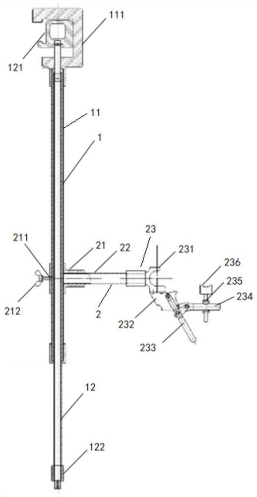
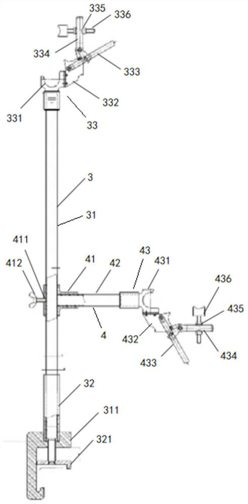
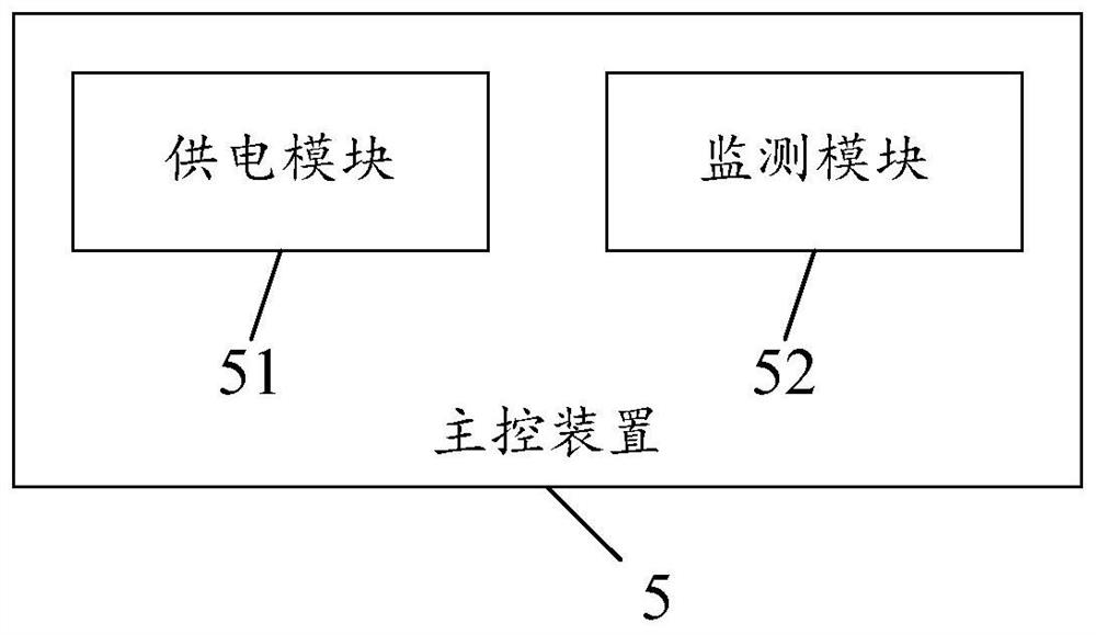
[0029] figure 1 is the first partial structural schematic diagram of the special support for the bypass drainage line in the embodiment of the present invention, figure 2 is the second partial structural schematic diagram of the special support for the bypass drainage line in the embodiment of the present invention, image 3 It is a schematic diagram of the composition of the main control device in the embodiment of the present inv...


PUM


Abstract

The invention discloses a special bracket for bypass drainage wires. The special bracket for bypass drainage wires includes a variable resistance side phase drainage wire bracket, a side phase drainage wire fixing device, a variable resistance middle phase drainage wire bracket, and a middle phase drainage wire fixing device. The device and the main control device, the main control device includes a power supply module and a monitoring module; the side-phase drain wire fixing device includes a side-phase magnetic suction sliding sleeve rod, a side-phase cross bar and a side-phase drain wire fixing assembly; the middle-phase drain wire fixing device It includes the mid-phase magnetic suction sliding sleeve rod, the mid-phase cross bar and the mid-phase drain wire fixing assembly. In the embodiment of the present invention, the special support for bypass drain wires can create a distance between the side phase drain wires and the ground potential device, between the middle phase drain wires and the insulated drain wires, and can also create a distance between the side phase drain wires and the ground potential device. Real-time monitoring is carried out on the distance between the middle-phase drain wire and the insulating drain wire to ensure that the distance between the side-phase drain wire and the ground potential device, and the distance between the middle-phase drain wire and the insulating drain wire reaches a safe distance.

Description

technical field [0001] The invention relates to the technical field of live maintenance on-site, in particular to a special support for bypass drainage lines. Background technique [0002] With the increasing reliability requirements of distribution network power supply and the improvement of live work rate indicators, live work has become an important means, and bypass live work is also widely carried out. The wire work method takes a lot of time and physical energy in the insulation shielding and fixing of the insulation drainage wire, and it takes about two hours for the single bypass system to be put into operation. To this end, a special bracket for bypass drainage line is introduced, which can make a certain distance between the side-phase drainage line and the ground potential device, and can also make the middle-phase drainage line and the insulation drainage line. There is a certain distance between them. However, the existing special bracket for bypass drainage li...

Claims


Application Information

Patent Timeline
Patent Type & Authority Patents(China)
IPC IPC(8): H02G1/02
CPCH02G1/02
Inventor 陈振华黄自韬李英新周康成吕金沂何达秋岑海昌黄亮夏杨甘罗旭韦超荣田启年杨程
Owner GUIGANG POWER SUPPLY BUREAU OF GUANGXI POWER GRID CO LTD
Learn More