
Wind turbine generator blade tip and tower drum distance monitoring method and system

A technology for wind turbines and towers, which is used in wind turbine monitoring, wind turbines, mechanical measuring devices, etc., can solve problems such as poor stability, damage to tower structure and paint film, and inconvenient maintenance.

Pending Publication Date: 2021-03-23
CHINA ELECTRIC POWER RES INST +1
View PDF0 Cites 0 Cited by
  • Summary
  • Abstract
  • Description
  • Claims
  • Application Information

AI Technical Summary

Problems solved by technology

[0003] At present, the existing monitoring technology for the distance between the tip of the wind turbine and the tower has problems such as inconvenient installation, maintenance, and poor stability. Moreover, in order to cover the yaw process, multiple ultrasonic sensors need to be installed at different angles.
In addition, since the sensor needs to be fixed on the outside of the tower (such as by bolts), it may cause damage to the tower structure and paint film

Method used


Image

  • Wind turbine generator blade tip and tower drum distance monitoring method and system
  • Wind turbine generator blade tip and tower drum distance monitoring method and system
  • Wind turbine generator blade tip and tower drum distance monitoring method and system

Examples


Embodiment 1

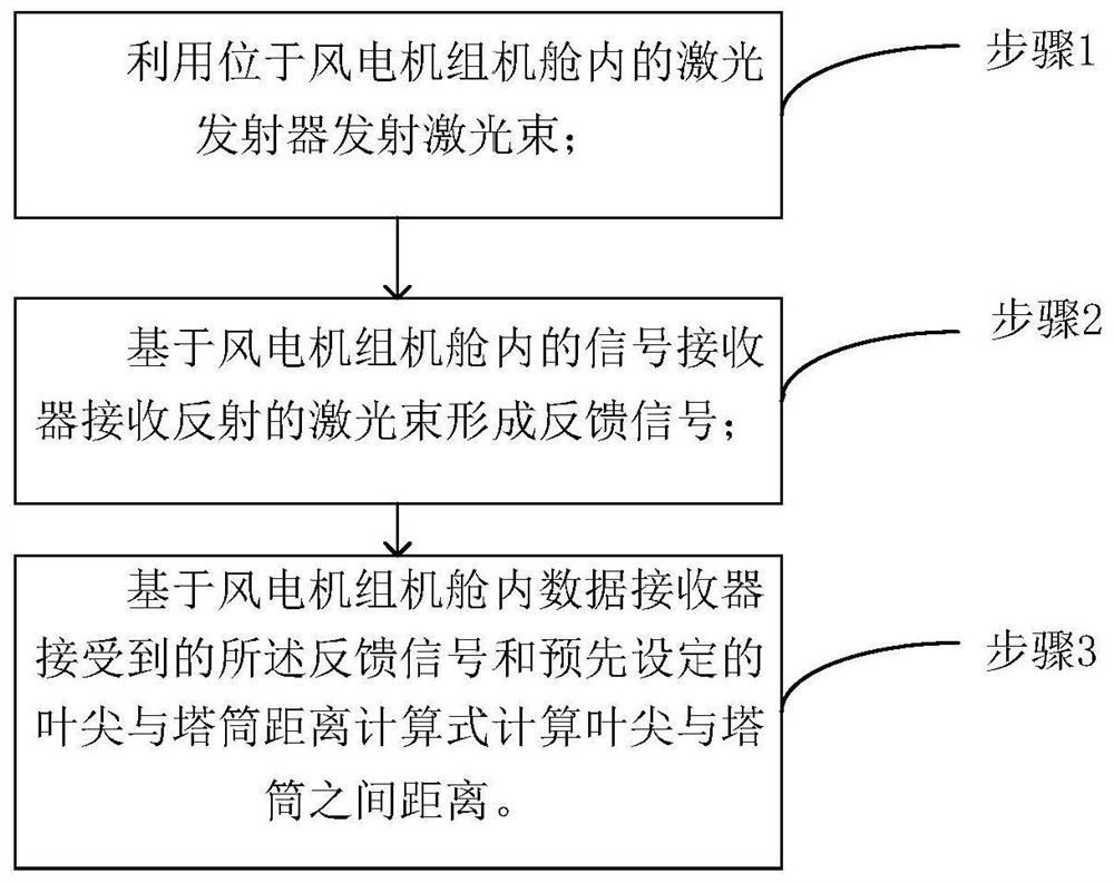
[0046] Such as figure 1 A method for monitoring the distance between the tip of the wind turbine and the tower includes:

[0047] Step 1: Use the laser transmitter located between the front tower and the blades in the wind turbine nacelle to emit a laser beam;

[0048] Step 2: Form a feedback signal based on the signal receiver in the wind turbine nacelle receiving the reflected laser beam;

[0049] Step 3: Calculate the distance between the blade tip and the tower based on the feedback signal received by the data receiver in the wind turbine nacelle and the preset formula for calculating the distance between the blade tip and the tower.

[0050] Among them, step 1 specifically includes: the installation position of the laser generator is in the front half of the nacelle, and the installation point is not unique. That is, it can be installed at the position of the nacelle bottom plate on the central axis of the nacelle, or at the position of the nacelle bottom plate on one s...

Embodiment 2

[0066] Based on the same idea, the present invention designs a wind turbine blade tip-tower distance monitoring system,

[0067] Laser generator, signal receiver and data collector;

[0068] The laser generator is installed between the front tower and the blades in the wind turbine nacelle for emitting laser beams;

[0069] The signal receiver is connected with the laser generator for receiving the feedback signal formed by the reflected laser beam;

[0070] The data collector is connected to the signal receiver for receiving the feedback signal transmitted by the signal receiver, and calculating and displaying the distance between the blade tip and the tower based on the feedback signal;

[0071] Both the signal receiver and the laser receiver are located inside the wind turbine nacelle.

[0072] Preferably, the bottom plate of the wind turbine cabin is provided with a hole, and the laser generator is fixed at the hole;

[0073] The hole is set at the central axis of the n...


PUM


Abstract

The invention discloses a wind turbine generator blade tip and tower drum distance monitoring method, which comprises the steps of using a laser emitter located between the tower drum and a blade on the front side in a cabin of the wind turbine generator for emitting laser beams, receiving the reflected laser beam based on a signal receiver in the cabin of the wind turbine generator to form a feedback signal, and calculating the distance between the blade tip and the tower drum based on the feedback signal received by the data receiver in the cabin of the wind turbine generator and a preset calculation formula of the distance between the blade tip and the tower drum. Installation and maintenance are facilitated, the distance between the blade tip and the tower drum is monitored in real time, and the safety of the wind turbine generator is improved.

Description

technical field [0001] The invention relates to the technical field of wind power generation, in particular to a method and system for monitoring the distance between a blade tip of a wind turbine and a tower. Background technique [0002] With the maturity of wind power technology, the wind power industry has entered a period of rapid growth. Correspondingly, the capacity and size of wind turbines continue to increase. Wind turbine blades are the main components of the entire wind turbine to absorb energy. With the application of new materials and new processes, the blades are designed to be lighter, longer, and softer, and their mechanical and aerodynamic performance have been greatly improved. However, under extreme wind conditions, the ultra-long flexible blades will have a large deformation, which may cause the tip of the blade to touch the tower, resulting in the risk of sweeping the tower, and then causing the tower to collapse. Therefore, in order to improve the st...

Claims


Application Information

Patent Timeline
IPC IPC(8): G01B11/14F03D17/00
CPCF03D17/00G01B5/003G01B11/14
Inventor 王安庆龚利策李松迪赵娜贾海坤付德义李婷王瑞明薛扬马晓晶
Owner CHINA ELECTRIC POWER RES INST
Learn More