

Novel transformer high-falling prevention device
A transformer and a new technology, applied in the field of transformers, can solve the problems of small range of activities, inconvenient movement, poor safety, etc., and achieve the effects of flexible use, easy portability, and convenient disassembly and assembly.
- Summary
- Abstract
- Description
- Claims
- Application Information
AI Technical Summary
Problems solved by technology
Method used
Image

Examples
Embodiment 1
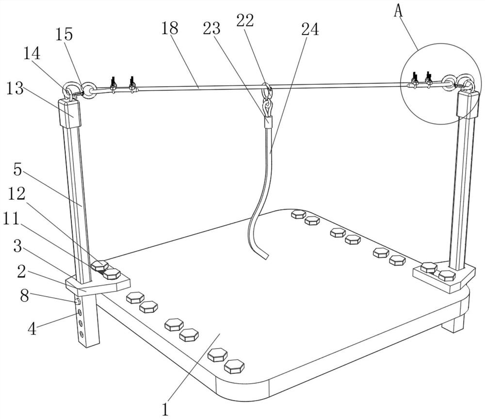
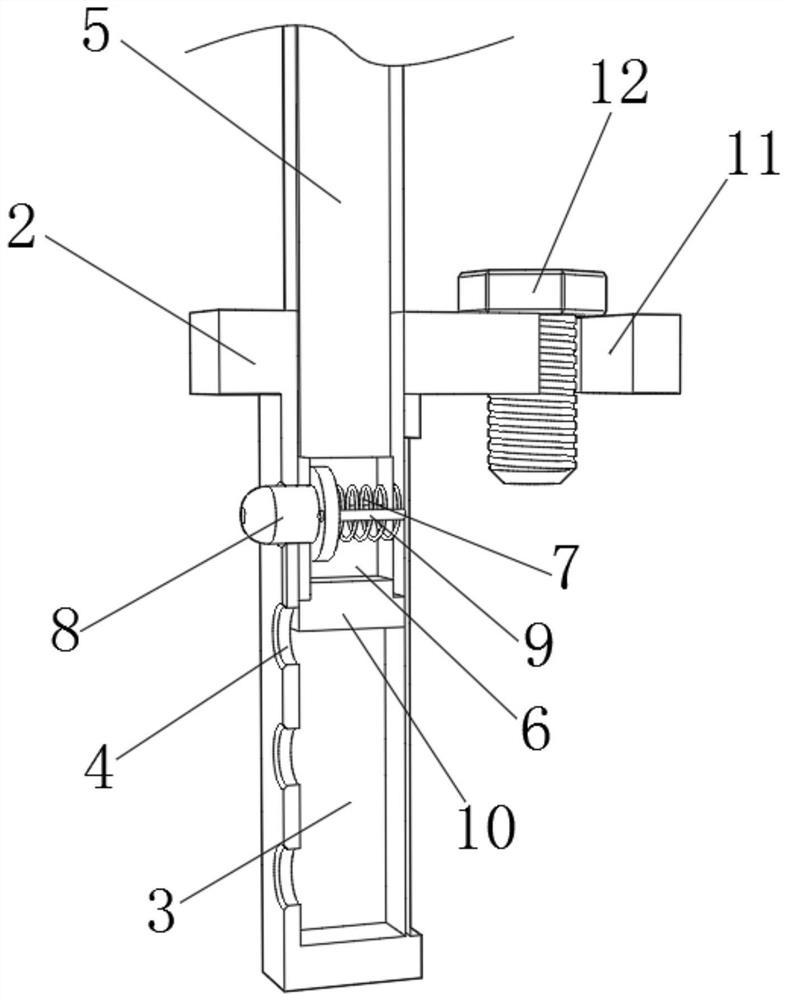
[0029] refer to Figure 1-Figure 3 , a new type of transformer high-falling device, including a top plate 1 and two quick-installation bases 2, the upper surface of the quick-installation base 2 is provided with an insertion slot 3, and an insulating rod 5 is inserted in the insertion slot 3, and the insulating rod 5 is plugged into the socket slot 3, and one side of the quick-mount base 2 is provided with a plurality of clamping holes 4, and the bottom end of the insulating rod 5 is provided with a mounting groove 6, and a guide rod 9 is slidably connected in the mounting groove 6, and the guide rod One end of 9 is fixed with the clamping shaft 8 by bolts. When the height of the insulating rod 5 needs to be adjusted, the clamping shaft 8 is pressed inward, and the clamping shaft 8 is clamped with the clamping hole 4, so that the clamping shaft 8 and the clamping hole 4 Separated, the first spring 7 is sleeved on one side of the guide rod 9, and then the insulating rod 5 is pr...
Embodiment 2
[0033] refer to Figure 4-Figure 5 , a new anti-falling device for transformers, including a chute 25 on one side of the quick-installation base 2, a support frame 26 slidingly connected in the chute 25, and a fixing plate fixed on one side of the quick-installation base 2 by bolts 27. The top of the fixing plate 27 is fixed with a second spring 28 by bolts, the other end of the second spring 28 is fixedly connected to one side of the support frame 26, and the two sides of the support frame 26 are respectively fixed with a mounting block 29 by bolts. The top of 29 is rotatably connected with rotating shaft 30, and the top of rotating shaft 30 is fixed with support block 31 by bolt, and wherein, support frame 26, fixed plate 27, second spring 28, mounting block 29, rotating shaft 30 and support block 31 The device is reinforced in conjunction with the setting, which improves the stability of the device during operation.
[0034] The working principle of this embodiment: when i...
PUM
 Abstract
Description
Claims
Application Information