A steel cutting device for conveniently fixing special-shaped steel

A special-shaped steel and cutting device technology, applied in metal processing equipment, welding equipment, manufacturing tools, etc., can solve the problems of low work efficiency, achieve the effects of improving work efficiency, simple operation, and improving stability

Active Publication Date: 2021-05-11
广州腾涟晟建材有限公司
View PDF6 Cites 0 Cited by
  • Summary
  • Abstract
  • Description
  • Claims
  • Application Information

AI Technical Summary

Problems solved by technology

[0004] In order to overcome the disadvantages of complex operation, multiple people are required to manually shift the steel and low work efficiency, the technical problem of the present invention is to provide a steel cutting device for conveniently fixing special-shaped steel that is easy to operate and improves the cutting efficiency of the device

Method used


Image

  • A steel cutting device for conveniently fixing special-shaped steel
  • A steel cutting device for conveniently fixing special-shaped steel
  • A steel cutting device for conveniently fixing special-shaped steel

Examples


Embodiment 1

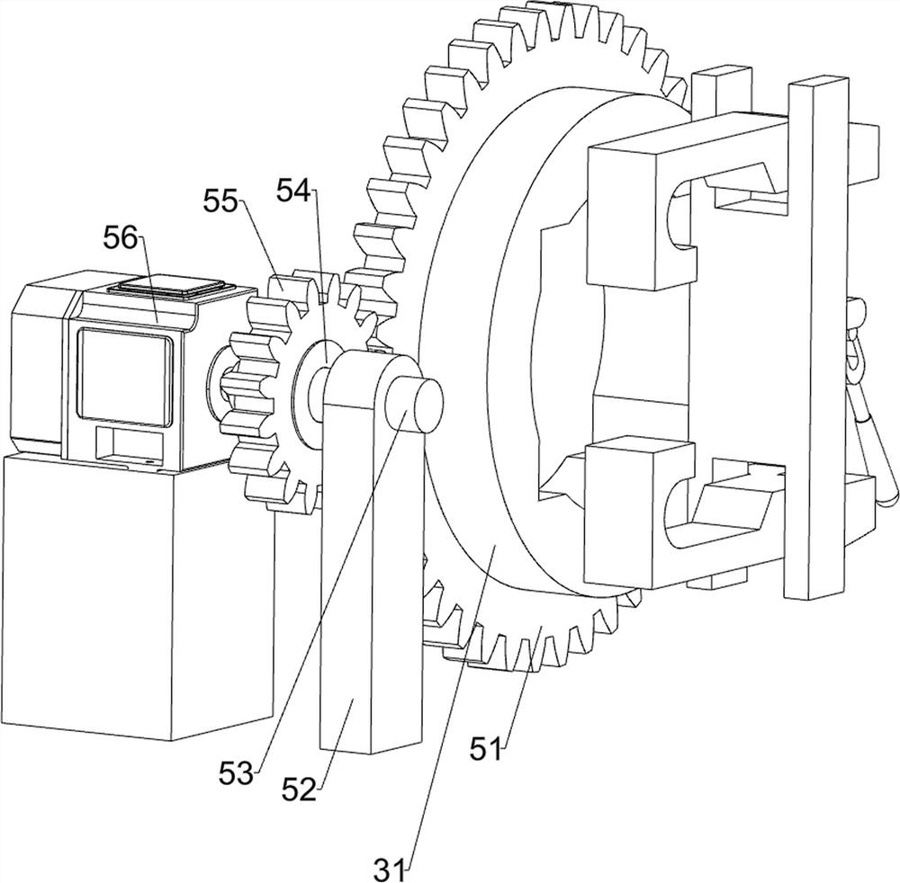
[0026] Such as figure 1 As shown, a steel cutting device for conveniently fixing special-shaped steel materials includes a bottom plate 1, a first bearing seat 2, a clamping mechanism 3, a moving mechanism 4 and a rotating mechanism 5, and the top of the bottom plate 1 is symmetrically provided with the first bearing seat 2, A clamping mechanism 3 is arranged in the middle of the first bearing seat 2 , a moving mechanism 4 is arranged on the top side of the bottom plate 1 , and a rotating mechanism 5 is connected to the middle part of the first bearing seat 2 and the clamping mechanism 3 .

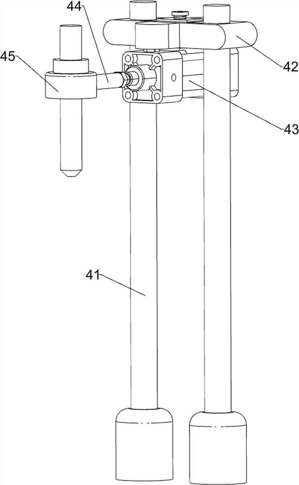
[0027] When the staff needs to fix the special-shaped steel for cutting, the special-shaped steel passes through the center of the two first bearing seats 2, and the pressing mechanism presses the two ends of the special-shaped steel respectively, and plasma nitrogen is used for cutting at one end of the special-shaped steel. For plasma melting cutting, the gas cutting torch 45 is driven b...

Embodiment 2

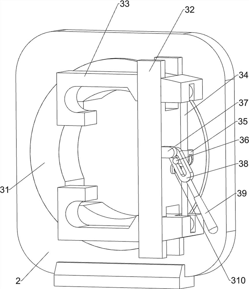
[0029] Such as figure 1 , figure 2 , image 3 and Figure 4 As shown, a steel cutting device for conveniently fixing special-shaped steel materials includes a bottom plate 1, a first bearing seat 2, a clamping mechanism 3, a moving mechanism 4 and a rotating mechanism 5, and the top of the bottom plate 1 is symmetrically provided with the first bearing seat 2, One of the first bearing seats 2 is slidingly matched with the bottom plate 1, a clamping mechanism 3 is arranged in the middle of the first bearing seat 2, a moving mechanism 4 is arranged on the top side of the bottom plate 1, and the middle part of the first bearing seat 2 is in phase with the clamping mechanism 3. A rotating mechanism 5 is connected.

[0030] Clamping mechanism 3 comprises circular ring 31, H-shaped block 32, special-shaped clamping block 33, connecting rod 34, U-shaped block 35, latch 36, holder 37, chute plate 38, handle 39 and limit block 310, two A ring 31 is rotatably arranged in the middle...

Embodiment 3

[0035] Such as Figure 5 and Figure 6 As shown, on the basis of Embodiment 2, a steel cutting device for conveniently fixing special-shaped steel also includes a side plate 6, a guide rail 7, a nut guide sleeve 8, a screw mandrel 9, a one-way clutch 10, a turntable 11, Guide blocks 12 and rollers 13, a side plate 6 is provided at the edge of the bottom plate 1 close to the first rotating shaft 53, and two guide rails 7 are symmetrically arranged on the side of the side plate 6 near the first rotating shaft 53, and the two guide rails 7 are slidingly arranged There is a nut guide sleeve 8, and the nut guide sleeve 8 is fixedly connected with the first bearing seat 2. The nut guide sleeve 8 is slidingly provided with a screw 9 in the middle of one side close to the guide rail 7. The first rotating shaft 53 and the screw rod 9 pass through the one-way clutch 10 Transmission connection, the end of the screw rod 9 away from the one-way clutch 10 is provided with a turntable 11, t...


PUM


Abstract

The invention relates to a cutting device, in particular to a steel material cutting device for conveniently fixing special-shaped steel materials. The invention provides a steel material cutting device for conveniently fixing special-shaped steel materials, which is simple in operation and improves the cutting work efficiency of the device. A steel cutting device for conveniently fixing special-shaped steel, comprising: a bottom plate, a first bearing seat is symmetrically arranged on the top of the bottom plate; a clamping mechanism, a clamping mechanism is arranged in the middle of the first bearing seat; a moving mechanism, a moving mechanism is arranged on one side of the top of the bottom plate mechanism; a rotating mechanism, the rotating mechanism is arranged in the middle of the first bearing seat, and the rotating mechanism is connected with the clamping mechanism. The clamping stability of special-shaped steel is improved through the setting of the dead point position of the two connecting rods, and the operation is simple.

Description

technical field [0001] The invention relates to a cutting device, in particular to a steel material cutting device for conveniently fixing special-shaped steel materials. Background technique [0002] There are various types and shapes of steel. For example, structural steel includes H-shaped steel, C-shaped steel, T-shaped steel, etc., and the shapes of the steel are not easy to fix. The compression method can only apply pressure to multiple places around the steel. The operation is complicated and every After cutting a section of steel workpiece, many people need to cooperate to manually shift the remaining steel, and then re-press all parts of the steel, which reduces the working efficiency of the steel cutting device. [0003] Therefore need to research and develop a kind of simple operation, the steel cutting device that improves device cutting work efficiency conveniently fixes special-shaped steel. Contents of the invention [0004] In order to overcome the disadva...

Claims


Application Information

Patent Timeline
Patent Type & Authority Patents(China)
IPC IPC(8): B23K7/00B23K7/10
CPCB23K7/00B23K7/10
Inventor 李颂
Owner 广州腾涟晟建材有限公司
Why Eureka
Try Eureka