
Gyro pendant production and processing equipment with positioning and automatic assembling functions

A technology for processing equipment and pendants, applied in the field of gyro pendant production and processing equipment, can solve problems such as inconvenient calibration and time-consuming bearings, and achieve the effect of improving production efficiency and avoiding rhythm.

Pending Publication Date: 2021-02-12
沈富春
View PDF0 Cites 0 Cited by
  • Summary
  • Abstract
  • Description
  • Claims
  • Application Information

AI Technical Summary

Problems solved by technology

[0004] Aiming at the deficiencies of the prior art, the present invention provides a gyro pendant production and processing equipment equipped with automatic positioning and assembly, which solves the problem of the combination of the thumb gyro and the keychain proposed in the background technology above, and the arrangement of personnel in different positions to form a flowing water The basic assembly is manual assembly, by manually pressing the bearing into the card slot of the main body, then covering the top of the bearing with the shell, and finally fixing the fixed block across the inner ring of the bearing on the outside of the shell, so that during assembly Due to the small size of the bearing, it is very time-consuming to install the main body groove, and when the fixing block is installed, the pendant needs to be placed under the equipment to be pressed and fixed, and it is inconvenient to calibrate every time it is pressed.

Method used


Image

  • Gyro pendant production and processing equipment with positioning and automatic assembling functions
  • Gyro pendant production and processing equipment with positioning and automatic assembling functions
  • Gyro pendant production and processing equipment with positioning and automatic assembling functions

Examples


Embodiment Construction

[0028] The following will clearly and completely describe the technical solutions in the embodiments of the present invention with reference to the accompanying drawings in the embodiments of the present invention. Obviously, the described embodiments are only some, not all, embodiments of the present invention.

[0029] In the description of the present invention, unless otherwise stated, the meaning of "plurality" is two or more; the terms "upper", "lower", "left", "right", "inner", "outer" , "front end", "rear end", "head", "tail", etc. indicate the orientation or positional relationship based on the orientation or positional relationship shown in the drawings, and are only for the convenience of describing the present invention and simplifying the description, rather than Indicates or implies that the device or element referred to must have a particular orientation, be constructed and operate in a particular orientation, and therefore should not be construed as limiting the...


PUM


Abstract

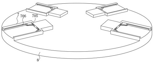
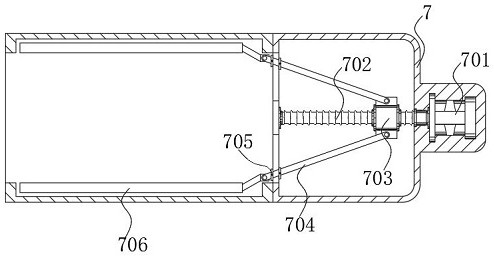
The invention discloses gyro pendant production and processing equipment with positioning and automatic assembling functions. The equipment comprises an assembling case, a main body pushing assembly is installed on the left side of the top of the assembling case, and a fixing block assembling mechanism is arranged in a gap between the right side end of an operation table and the right side end ofa shell pushing assembly. According to the equipment, main body positioning clamps are symmetrically arranged on the top end face of the operation table in a crossed mode, the bottoms of the main bodypositioning clamps and flow guide grooves of the main body pushing assembly and the shell pushing assembly are formed in the same horizontal line, and therefore a main body can be conveniently pushedinto the main body positioning clamps to be positioned and clamped; and a bearing mounting assembly and the fixing block assembling mechanism are arranged at the top and the bottom of the operation table respectively, so that a shell and the main body are fixed through a fixing block penetrating through a bearing after the bearing and the main body are arranged, the situation that during manual mounting, the rhythm is slowed, and then the production efficiency is reduced is avoided, and then personnel saving and production efficiency improving are facilitated.

Description

technical field [0001] The invention relates to the technical field of gyro pendants, in particular to a production and processing equipment for gyro pendants equipped with automatic positioning and assembly. Background technique [0002] The fidget spinner is a small toy with a bearing symmetrical structure that can spin on the fingers. It is composed of a two-way or multi-directional symmetrical body as the main body, and a design combination of bearings is embedded in the middle of the main body. The whole constitutes a planar rotating A new type of item, the basic principle of this item is similar to the traditional spinning top, but it needs to be grasped and moved by a few fingers to make it rotate, and the fidget spinner is very popular among young people because of its small size and convenient operation. The combination of the fidget spinner and the keychain serves as a pendant, which not only plays an aesthetic role, but also plays with it in spare time. [0003] ...

Claims


Application Information

Patent Timeline
Patent Type & Authority Applications(China)
IPC IPC(8): B23P19/00B23P19/02
CPCB23P19/001B23P19/02
Inventor 沈富春
Owner 沈富春
Learn More