A wire-actuated segment capable of decoupling bending motion

A technology of bending motion and structural joints, applied in the field of robotics, can solve problems such as increasing the difficulty of control

Active Publication Date: 2022-02-08
CHANGSHA UNIVERSITY OF SCIENCE AND TECHNOLOGY
View PDF6 Cites 0 Cited by
  • Summary
  • Abstract
  • Description
  • Claims
  • Application Information

AI Technical Summary

Problems solved by technology

The above-mentioned document discloses a mechanical arm composed of an end disk, a base disk and a spacer disk. The mechanical arm has two degrees of freedom and can be driven by a rod. However, during the bending process of the driving mechanical arm, the two degrees of freedom There is coupling in the bending direction of 1 degree, when bending the rod in one direction, the rod in the other direction will also bend, which will increase the difficulty of control

Method used


Image

  • A wire-actuated segment capable of decoupling bending motion
  • A wire-actuated segment capable of decoupling bending motion
  • A wire-actuated segment capable of decoupling bending motion

Examples


Embodiment 1

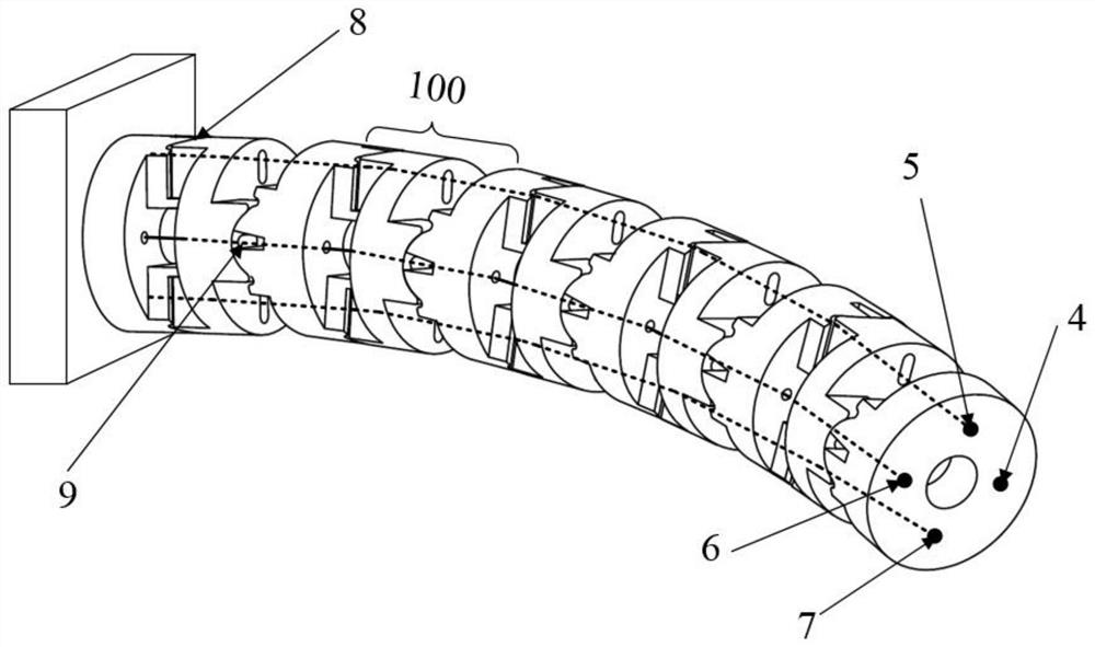
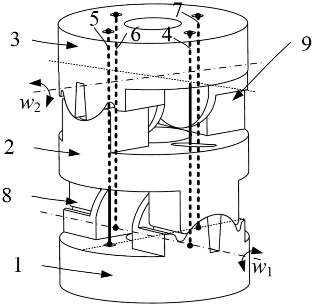
[0034] Such as figure 1 with figure 2 As shown, this embodiment provides a wire-driven joint that can realize decoupling of bending motion, including a plurality of wire-driven joints 100 connected end-to-end, first wires and second wires of each wire-driven joint 100 connected in series; The wire-driven joint 100 includes a base plate 1, a connecting rod 2 and an end plate 3, the base plate 1 is connected with the connecting rod 2 and forms a first rotating pair 8, the rotation axis of the first rotating pair 8 is in line with The end face of the base plate 1 coincides; the end plate 3 is connected with the connecting rod 2 to form a second rotating pair 9, and the rotation axis of the second rotating pair 9 coincides with the end face of the end plate 3; The first wire sequentially passes through each wire-driven joint 100 and drives the second rotating pair 9 to rotate, and the second wire passes through each wire-driven joint 100 sequentially and drives the first rotatin...

Embodiment 2

[0045] Such as figure 1 with figure 2 As shown, this embodiment provides a wire-driven joint that can realize decoupling of bending motion, including a plurality of wire-driven joints 100 connected end-to-end, first wires and second wires of each wire-driven joint 100 connected in series; The wire-driven joint 100 includes a base plate 1, a connecting rod 2 and an end plate 3, the base plate 1 is connected with the connecting rod 2 and forms a first rotating pair 8, the rotation axis of the first rotating pair 8 is in line with The end face of the base plate 1 coincides; the end plate 3 is connected with the connecting rod 2 to form a second rotating pair 9, and the rotation axis of the second rotating pair 9 coincides with the end face of the end plate 3; One end of the first wire is fixedly connected to the end disk 3 at the tail end of the wire driving joint, and the other end passes through the end disk 3, the connecting rod 2, the first rotating pair 8 and the base disk...


PUM


Abstract

The invention discloses a wire-driven joint capable of decoupling bending motion, comprising at least two wire-driven joints connected end to end, a first wire and a second wire connected in series to each wire-driven joint; the wire-driven joint includes a basic A base plate, a connecting rod and an end plate, the base plate is connected with the connecting rod to form a first rotating pair, the rotation axis of the first rotating pair coincides with the end surface of the base plate; the end plate Connected with the connecting rod to form a second rotating pair, the rotation axis of the second rotating pair coincides with the end face of the end disc; the first wire passes through each wire driving joint in turn and drives the second rotating pair to rotate , the second wire passes through each wire-driven joint in turn and drives the first revolving pair to rotate. The wire-driven structural member can realize bending decoupling motion in two degrees of freedom, which can effectively simplify the robot kinematics and reduce the difficulty of control.

Description

technical field [0001] The invention relates to the field of robots, in particular to a wire-driven structural section capable of decoupling bending motion. Background technique [0002] Since the wire-driven serpentine arm robot can realize multi-degree-of-freedom bending motion, it can work flexibly in a complex environment with limited height, and is widely used in maintenance inspection, minimally invasive surgery and other fields. In recent years, the types of joints that can be used to construct wire-driven snake-arm robots are rich and diverse. According to the joint degrees of freedom, they can be divided into single-degree-of-freedom or two-degree-of-freedom. The common single-degree-of-freedom joints include single-degree-of-freedom fixed-axis rotary joints, Plate and cylindrical rolling joints, etc.; two-degree-of-freedom joints include axis intersecting type (universal joint / ball joint) fixed axis rotating joint, axis non-intersecting fixed axis rotating joint, f...

Claims


Application Information

Patent Timeline
Patent Type & Authority Patents(China)
IPC IPC(8): B25J9/06B25J17/00
CPCB25J9/065B25J17/00
Inventor 黄龙刘北张鹏段超尹来容
Owner CHANGSHA UNIVERSITY OF SCIENCE AND TECHNOLOGY
Why Eureka
Try Eureka