Variable range of motion and variable length spine modules

A motion range and spine technology, applied in the field of bionic robots, can solve the problems of high energy consumption, irrespective of the deformation of system components, complex dynamic shape, etc., to achieve the effect of small impact and increased range of motion

Active Publication Date: 2018-05-18
HARBIN ENG UNIV
View PDF8 Cites 0 Cited by
  • Summary
  • Abstract
  • Description
  • Claims
  • Application Information

AI Technical Summary

Problems solved by technology

[0002] At present, most of the research on the spine of bionic multi-legged robots is based on the rigid torso as a model, without considering the deformation of system components, and it is impossible to achieve active control and drive of the spine, only passive drive
In fact, the muscles, tendons and ligaments of moving organisms can store and release energy like springs, and they have flexible deformation during movement, and their dynamic shapes are complex.
Especially for running and jumping creatures, if a purely rigid model is used, it must not be able to reasonably explain the mechanical properties of the biological movement, and the passively driven spine model will inevitably lead to a large energy consumption during the movement process, resulting in energy loss during the movement process. The utilization rate decreases, so that the robot has great limitations in the speed and efficiency of fast walking

Method used


Image

  • Variable range of motion and variable length spine modules
  • Variable range of motion and variable length spine modules

Examples


Embodiment Construction

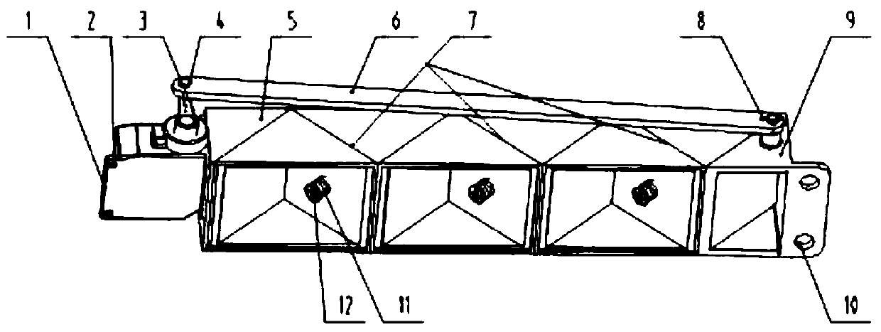
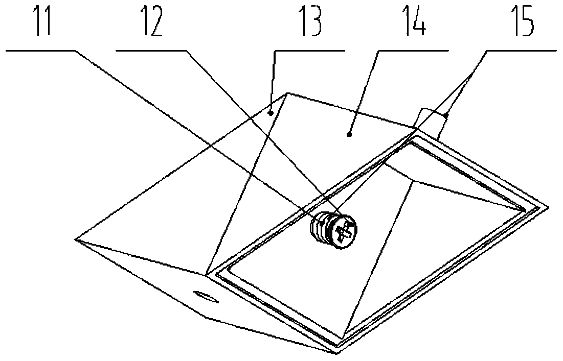
[0012] The present invention will be further described in detail below in conjunction with the accompanying drawings and specific embodiments.

[0013] combine Figure 1 to Figure 2 , the present invention comprises a steering gear 1, a fixing hole 2, a rudder angle 3, a rotating shaft 4, a spine section 5, a connecting rod 6, a spine module 7, a pin shaft 8, a spine section 2 9, a fixing hole 10, a spring 11, Screw 12, front spinal segment 13, rear spinal segment 14, connecting column 15. Specifically: if figure 1 As shown, there is a fixing hole-2 on one side of the steering gear 1, which can be fixed on the front end of the torso of the quadruped robot, and the other side is fixed on the spine joint-5. One end of the connecting rod 6 is connected with the rudder horn 3 through the rotating shaft 4, and the other end is connected with the second spine joint 9 through the pin shaft 8. The second spine section 9 is fixed on the trunk rear end of the quadruped robot through ...


PUM


Abstract

The invention provides a spine module with a changeable motion amplitude and a changeable length. The spine module comprises a steering engine, a rudder angle, a first spine joint, spine module bodies, a second spine joint and a connecting rod. The steering engine is installed at the end of the first spine joint. One end of the connecting rod is hinged to the rudder angle arranged on the steering engine through a rotating shaft, and the other end of the connecting rod is hinged to the second spine joint through a pin shaft. The spine module bodies are arranged between the first spine joint and the second spine joint. The spine module bodies comprise front spine joints and rear spine joints. Connecting cylinders are arranged on the rear spine joints. Round holes matched with the connecting cylinders are formed in the front spine joints. The connecting cylinders are sleeved with springs, and screws are arranged at the ends of the connecting cylinders. The connecting manner between the first spine joint and the spine module bodies, the connecting manner between the second spine joint and the spine module bodies and the connecting manner between the front spine joints and the rear spine joints are the same. The spine module with the changeable motion amplitude and the changeable length is simple in structure, the impact on a mechanism is small, and enlarging of the motion range of legs of a quadruped robot can be facilitated.

Description

technical field [0001] The invention relates to a spine module, in particular to a spine module with variable motion range and variable length, which is suitable for the field of bionic robots. Background technique [0002] At present, most of the researches on the spine of bionic multi-legged robots are based on the rigid torso as the model, without considering the deformation of system components, and the spine cannot be actively controlled and driven, but only passively driven. In fact, the muscles, tendons and ligaments of moving organisms can store and release energy like springs, and they have flexible deformation during movement and complex dynamic forms. Especially for running and jumping creatures, if a purely rigid model is used, it must not be able to reasonably explain the mechanical properties of the biological movement, and the passively driven spine model will inevitably lead to a large energy consumption during the movement process, resulting in energy loss d...

Claims


Application Information

Patent Timeline
Patent Type & Authority Patents(China)
IPC IPC(8): B25J9/00
CPCB25J9/0006
Inventor 陈东良周凯庄博王博张志远刘冲陈磊汪永远李宁杰段鹏
Owner HARBIN ENG UNIV
Why Eureka
Try Eureka