Injection mold with limiting structure

A technology of injection mold and limit structure, which is applied in the field of injection mold, can solve the problems of upper mold and lower mold impact, affect the quality of injection molded parts, increase the unqualified rate, etc., and achieve the effect of improving the qualified rate, preventing displacement and maintaining quality

Pending Publication Date: 2021-02-12
徐艳慧
View PDF0 Cites 2 Cited by
  • Summary
  • Abstract
  • Description
  • Claims
  • Application Information

AI Technical Summary

Problems solved by technology

[0003] Most of the current injection molds are not equipped with limit devices, and some injection molds with limit devices are relatively simple in structure and cannot meet the requirements of more and more refined production. Pouring into between the upper mold and the lower mold will cause impact on the upper mold and the lower mold. At the same time, the high-temperature raw material will also heat the mold. Due to thermal expansion and contraction, displacement may occur between the upper mold and the lower mold. , thus affecting the quality of injection molded parts, greatly increasing the failure rate and increasing the production cost

Method used


Image

  • Injection mold with limiting structure
  • Injection mold with limiting structure
  • Injection mold with limiting structure

Examples


Embodiment Construction

[0021] The following examples are for illustrative purposes only and are not intended to limit the scope of the invention.

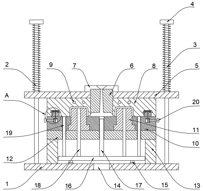
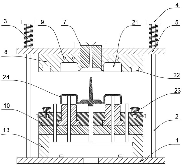
[0022] refer to Figure 1-4 , an injection mold with a position-limiting structure, comprising a lower base plate 1, straight rods 2 are welded and fixed at the top four corners of the lower base plate 1, the top of the straight bar 2 is welded and fixed with a limit block 4, and the bottom of the limit block 4 is welded and fixed There is a return spring 3, the straight rod 2 is slidingly connected with an upper baffle 5, the other end of the return spring 3 is welded and fixed on the upper baffle 5, the return spring 3 is sleeved on the straight rod 2, and the bottom of the upper baffle 5 is welded and fixed with an upper Die 8, the top of lower bottom plate 1 is welded and fixed with support block 13, and support plate 12 is fixed with bolt above support block 13, and support plate 12 top is provided with fixed plate 10, and fixed plate 10 is connecte...


PUM


Abstract

The invention discloses an injection mold with a limiting structure. The injection mold with the limiting structure comprises a lower bottom plate; straight rods are fixedly welded to the four cornersof the top of the lower bottom plate correspondingly; limiting blocks are fixedly welded to the tops of the straight rods; reset springs are fixedly welded to the bottoms of the limiting blocks; an upper baffle is connected to the straight rods in a sliding mode; the other ends of the reset springs are welded and fixed to the upper baffle; the reset springs are arranged on the straight rods in asleeving mode; upper molds are fixed to the bottom of the upper baffle; a supporting block is welded and fixed to the upper portion of the lower bottom plate; a supporting plate is fixed to the upperportion of the supporting block through bolts; a fixing plate is arranged above the supporting plate; a lower mold is connected to the fixing plate; a sprue bush is connected to the central position of the upper baffle; a positioning ring is connected to the top end of the sprue bush; and pouring cavities are formed in the upper molds. The injection mold with the limiting structure has the advantages that the triangular sliding block slides outwards by rotating a knob, so that the upper molds and the fixing plate are limited, the mold is prevented from displacing, and the quality of a producedinjection molding part is kept.

Description

technical field [0001] The invention relates to the technical field of injection molds, in particular to an injection mold with a position-limiting structure. Background technique [0002] Injection mold is a tool for producing plastic products, and it is also a tool for giving plastic products complete structure and precise dimensions. Injection molding, also known as injection molding, is a molding method of injection and molding. Injection molding is a processing method used in the mass production of certain complex-shaped parts. Specifically, it refers to injecting the heated and melted plastic into the mold cavity under high pressure from the injection molding machine, and after cooling and solidifying, a molded product is obtained. The advantages of the injection molding method are fast production speed, high efficiency, automatic operation, various designs and colors, simple to complex shapes, large to small sizes, accurate product sizes, easy replacement of product...

Claims


Application Information

Patent Timeline
IPC IPC(8): B29C45/26B29C45/40
CPCB29C45/2606B29C45/4005
Inventor 徐艳慧
Owner 徐艳慧
Why Eureka
Try Eureka