Road bridge crack reinforcing structure and reinforcing method thereof

A technology for strengthening structures and cracks, which is applied in the direction of bridge reinforcement, roads, bridges, etc., can solve the problems of steel structure adjustment, poor gap repair effect, and inability to adapt to cracks, etc., to improve reliability, strengthen reliability, and increase contact range Effect

Inactive Publication Date: 2021-02-12
SUQIAN FENGCHI SECURITY & PROTECTION
View PDF5 Cites 0 Cited by
  • Summary
  • Abstract
  • Description
  • Claims
  • Application Information

AI Technical Summary

Problems solved by technology

[0003] In order to make up for the above deficiencies, the present invention provides a road bridge crack reinforcement structure, which aims to improve the poor repair effect of the gap, the steel structure cannot be adjusted, and the cracks of different widths and depths cannot be adapted, resulting in poor practicality.

Method used


Image

  • Road bridge crack reinforcing structure and reinforcing method thereof
  • Road bridge crack reinforcing structure and reinforcing method thereof
  • Road bridge crack reinforcing structure and reinforcing method thereof

Examples


Embodiment 1

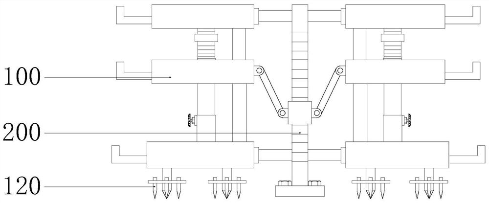
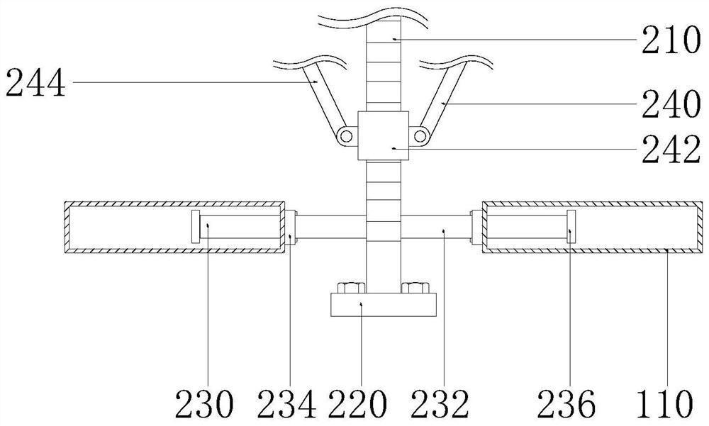
[0037] see Figure 1-5 , the present invention provides a technical solution: a road bridge crack reinforcement structure includes a fixing assembly 100 and a connecting assembly 200 .

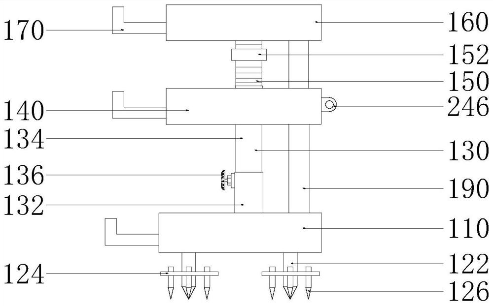
[0038] see Figure 1-5 , the fixing assembly 100 includes a bottom plate 110, a tightening member 120, an adjusting rod 130, a fixing plate 140, a threaded rod 150, a top plate 160, a fixing block 170 and a connecting pipe 190, the tightening member 120 is connected to the bottom of the base plate 110, and the adjusting rod 130 Connected above the bottom plate 110 , the fixed plate 140 is connected above the adjusting rod 130 , the fixed plate 140 is provided with a threaded hole 142 , and the threaded rod 150 is threadedly connected with the fixed plate 140 through the threaded hole 142 . The threaded rod 150 is threaded on the upper surface of the fixing plate 140 , and the threaded rod 150 is fixed with an adjusting block 152 , and the adjusting block 152 is fixedly sleeved on the outer su...

Embodiment 2

[0041] see Figure 1-5 , the present invention provides a technical solution: a road bridge crack reinforcement structure includes a fixing assembly 100 and a connecting assembly 200 .

[0042] see Figure 1-5 , the fixing assembly 100 includes a bottom plate 110, a tightening member 120, an adjusting rod 130, a fixing plate 140, a threaded rod 150, a top plate 160, a fixing block 170 and a connecting pipe 190, the tightening member 120 is connected to the bottom of the base plate 110, and the tightening member 120 includes an insertion rod 122 and a connection plate 124 , the insertion rod 122 is fixedly connected under the bottom plate 110 , and the connection plate 124 is fixed on the insertion rod 122 . The provision of the inserting rod 122 is conducive to a more reliable connection between the bottom plate 110 and the foundation. Connecting plate 124 is connected with post 126, and there are multiple posts 126. Setting post 126 helps to increase the contact range betwe...


PUM


Abstract

The invention provides a road and bridge crack reinforcing structure, and belongs to the technical field of road and bridge maintenance. The road and bridge crack reinforcing structure comprises a fixing assembly and a connecting assembly. The inserting piece is connected to the lower portion of the bottom plate, the adjusting rod is connected to the upper portion of the bottom plate, the threadedrod is connected to the upper surface of the fixing plate in a threaded mode, the connecting pipe is communicated with the pouring hole, and the connecting pipe penetrates through the fixing plate and the bottom plate. The base is connected to the bottom end of the lead screw, the connecting piece penetrates through the lead screw, the connecting piece is connected with the bottom plate and the top plate, one end of the reinforcing piece is hinged to the lead screw, and the other end of the reinforcing piece is connected with the fixing plate. The gap repairing effect can be improved, the size of the steel structure can be adjusted, the reinforcing requirements of cracks with different widths and depths can be met, and the practicability of the steel structure is improved.

Description

technical field [0001] The invention relates to the field of road and bridge maintenance, in particular to a road and bridge crack reinforcement structure. Background technique [0002] After a long period of exposure to wind and sun, road bridges will have cracks and need to be repaired manually. The existing crack reinforcement work for road bridges can be roughly divided into two types, one is pouring reinforcement, the other is steel structure reinforcement, and The two reinforcement methods cannot be used in combination with each other, and there are certain limitations in use, which affects the repair effect of the gap. At the same time, most of the existing steel structure reinforcement methods themselves adopt an integrated structure, resulting in the inability to adjust the steel structure. It cannot adapt to cracks of different widths and depths, resulting in poor practicality. How to invent a road bridge crack reinforcement structure to improve these problems has ...

Claims


Application Information

Patent Timeline
Patent Type & Authority Applications(China)
IPC IPC(8): E01D22/00E01C23/09
CPCE01D22/00E01C23/09
Inventor 李庆群
Owner SUQIAN FENGCHI SECURITY & PROTECTION
Why Eureka
Try Eureka