
Anti-blocking device for shower room drain pipe

A drainage pipe and anti-clogging technology, applied in the field of floor drains in shower rooms, can solve problems such as clogging of drainage holes and inability to drain water, and achieve the effects of reducing clogging, preventing clogging and solving clogging of water pipes

Active Publication Date: 2021-02-12
浙江艾希德新材料科技有限公司
View PDF8 Cites 0 Cited by
  • Summary
  • Abstract
  • Description
  • Claims
  • Application Information

AI Technical Summary

Problems solved by technology

[0004] Aiming at the deficiencies of the prior art, the present invention provides an anti-clogging device for the drain pipe of a shower room, which solves the problem that the existing floor drain often encounters the problem of hair blocking the drain hole and failing to drain water when draining.

Method used


Image

  • Anti-blocking device for shower room drain pipe
  • Anti-blocking device for shower room drain pipe
  • Anti-blocking device for shower room drain pipe

Examples


Embodiment 1

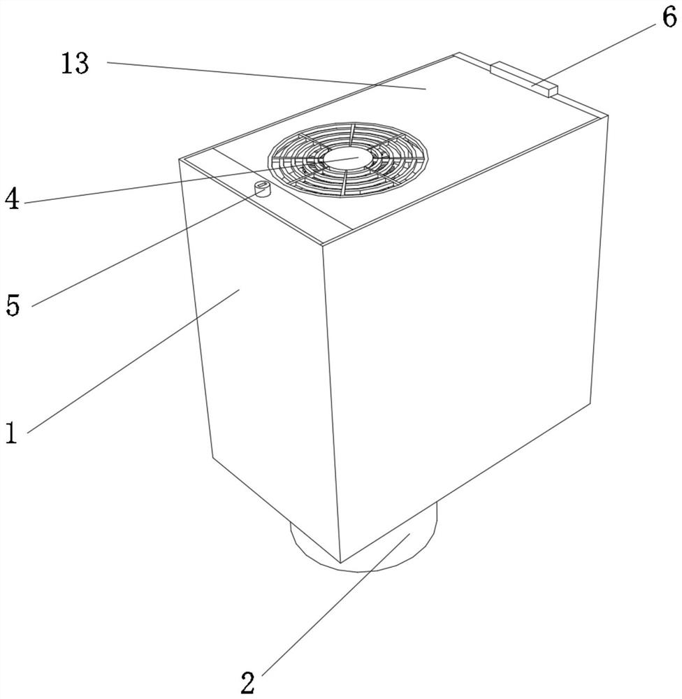
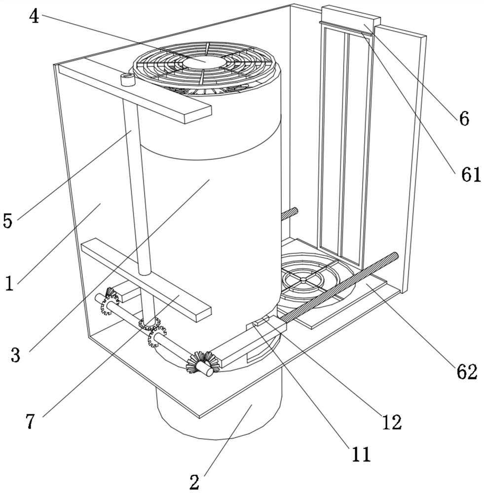
[0032] An anti-clogging device for shower room drain pipes, such as Figure 1-Figure 3 As shown, it includes a housing 1, the lower surface of the housing 1 is fixedly connected with a drain pipe body 2, the bottom wall inside the housing 1 is fixedly connected with an outer pipe 3, and the top of the outer pipe 3 is provided with an anti-blocking mechanism 4, and the inside of the housing 1 is provided with There is a transmission mechanism 5, the surface of the shell 1 is clamped with a clamping plate 6, the inner wall of the shell 1 is fixedly connected with a horizontal plate 7, the surface of the transmission mechanism 5 is in contact with a collection box 11, and the surface of the collection box 11 is fixedly connected with an ear piece 12.

[0033] In this embodiment, a case cover 13 is rotatably connected to the surface of the casing 1, and a through groove is opened on the surface of the case cover 13.

[0034] The inside of the shell 1 can be protected by the case c...

Embodiment 2

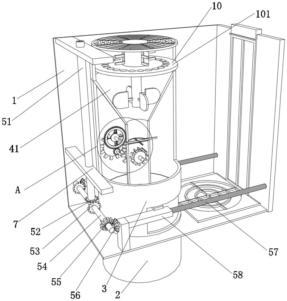
[0039] Such as Figure 4-Figure 8 As shown, on the basis of Embodiment 1, in this embodiment, the anti-blocking mechanism 4 includes an inner pipe 41, the surface of the inner pipe 41 is fixedly connected to the top of the outer pipe 3, and the inner wall of the inner pipe 41 is inserted with a first Rotating rod 42, the rear end of the first rotating rod 42 runs through the inside of the inner pipe 41 and is connected to the inner wall of the outer pipe 3 in rotation. The surface of the rotating rod 42 is fixedly connected to the outside of the inner pipe 41 with a first transmission gear 44, the surface of the first transmission gear 44 is meshed with a second transmission gear 45, and the axis of the second transmission gear 45 is fixedly connected with a second rotation gear. Rod 46, the two ends of the second rotating rod 46 are all rotatably connected with the inner wall of the outer pipe 3, the surface of the second rotating rod 46 is fixedly connected with the front po...


PUM


Abstract

The invention relates to the technical field of shower room floor drains, and discloses an anti-blocking device for a shower room drain pipe. The device comprises a shell; a drainage pipe body is fixedly connected with the lower surface of the shell; an outer pipeline is fixedly connected with the bottom wall inside the shell; an anti-blocking mechanism is arranged at the top of the outer pipeline; a transmission mechanism is arranged in the shell; a clamping plate is clamped to the surface of the shell; a transverse plate is fixedly connected with the inner wall of the shell; a collecting boxis in contact with the surface of the transmission mechanism; and a lug block is fixedly connected with the surface of the collecting box. According to the anti-blocking device for the shower room drain pipe, the anti-blocking mechanism is driven by water flow generated when a bather takes a bath, so that the anti-blocking mechanism can be started to collect hair generated when the bather takes abath in a unified mode, the situation that the hair blocks a drainage hole, and the drainage hole cannot drain water is prevented, the problem that a water pipeline is blocked is solved, and indoor peculiar smell caused by blockage is reduced.

Description

technical field [0001] The invention relates to the technical field of shower room floor drains, in particular to an anti-blocking device for shower room drain pipes. Background technique [0002] The floor drain is a common item in daily life. It is mainly installed in the bathroom. Its main function is to collect the water in the bathroom and discharge it into the building drainage system. The floor drain is an important interface connecting the drainage pipe system and the indoor ground. An important part of the system, its performance directly affects the quality of the indoor air, and is very important for the odor control in the bathroom. [0003] Existing floor drains are draining water, especially when bathrooms are used for bathing and draining. Hair often blocks the drain hole and cannot drain water. However, if the drain hole is directly enlarged to allow hair to enter the sewer pipe, it is possible The situation that the sewer pipe is blocked, and the blockage w...

Claims


Application Information

Patent Timeline
Patent Type & Authority Applications(China)
IPC IPC(8): E03F5/04E03F5/06E03F5/26E03F5/14B01D35/02B01D35/16
CPCE03F5/0408E03F5/06E03F5/26E03F5/14B01D35/02B01D35/16
Inventor 俞人炜
Owner 浙江艾希德新材料科技有限公司
Learn More