Self-adjusting protective guard special for building construction
A self-adjusting technology for building construction, which is applied in the direction of architecture, building type, building structure, etc., and can solve problems such as inability to automatically adjust
- Summary
- Abstract
- Description
- Claims
- Application Information
AI Technical Summary
Problems solved by technology
Method used
Image
Examples
Embodiment 1
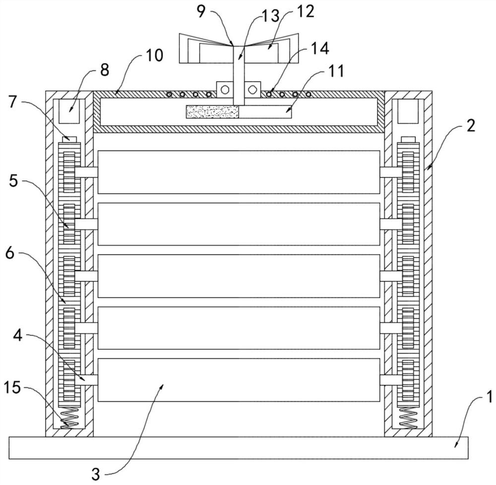
[0019] Such as figure 1 As shown, a special self-adjusting guardrail for building construction includes a base 1, two support cylinders 2 are fixedly installed on the upper surface of the base 1, and a plurality of equidistantly arranged windshields 3 are arranged between the two support cylinders 2. Both ends of the windshield 3 are rotationally connected to the support cylinder 2 through the rotating shaft 4, and the rotating shaft 4 is located at one end of the supporting cylinder 2 and is coaxially fixed with a gear 5, and a vertically arranged rack 6 is slid inside the supporting cylinder 2. The lower end is fixedly connected to the inner bottom surface of the support tube 2 through the spring 15, the gear 5 meshes with the rack 6, the upper end of the rack 6 is fixedly connected with an iron block 7, and the inner top surface of the support tube 2 is fixedly connected with a block facing the iron block 7. The electromagnet 8.
[0020] The supporting cylinder 2 is provid...
Embodiment 2
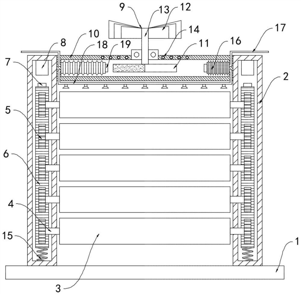
[0025] Such as figure 2 As shown, the difference between this embodiment and Embodiment 1 is that bellows 16 are fixedly connected to the inner walls on both sides of the housing 10, and the bellows 16 are fixedly connected with a one-way water inlet pipe 17 and a one-way drain pipe. 18. The water inlet end of the one-way water inlet pipe 17 extends to the drainage channel of the construction site, and the discharge end of the one-way drain pipe 18 extends directly above the windproof plate 3, and the end of the corrugated pipe 16 near the bar magnet 11 is installed with a permanent magnet Block 19, the magnetic poles at two ends of the bar magnet 11 are opposite.
[0026] In this embodiment, when the wind fan 12 drives the bar magnet 11 to rotate, the N pole and the S pole of the bar magnet 11 approach and move away from the permanent magnet block 19 periodically, that is, the permanent magnet block 19 is periodically changed. Attraction and repulsion drive the bellows 16 t...
PUM
 Abstract
Description
Claims
Application Information
 - R&D
- Intellectual Property
- Life Sciences
- Materials
- Tech Scout
- Unparalleled Data Quality
- Higher Quality Content
- 60% Fewer Hallucinations
Browse by: Latest US Patents, China's latest patents, Technical Efficacy Thesaurus, Application Domain, Technology Topic, Popular Technical Reports.
© 2025 PatSnap. All rights reserved.Legal|Privacy policy|Modern Slavery Act Transparency Statement|Sitemap|About US| Contact US: help@patsnap.com


