[0029]The specific embodiments of the present invention will be described in detail below with reference to the accompanying drawings, but it should be understood that the protection scope of the present invention is not limited by the specific embodiments.
[0030]Unless otherwise expressly stated otherwise, throughout the specification and claims, the term "comprising" or its transformations such as "including" or "including" will be understood to include the stated elements or components, and not Other elements or other components are not excluded.
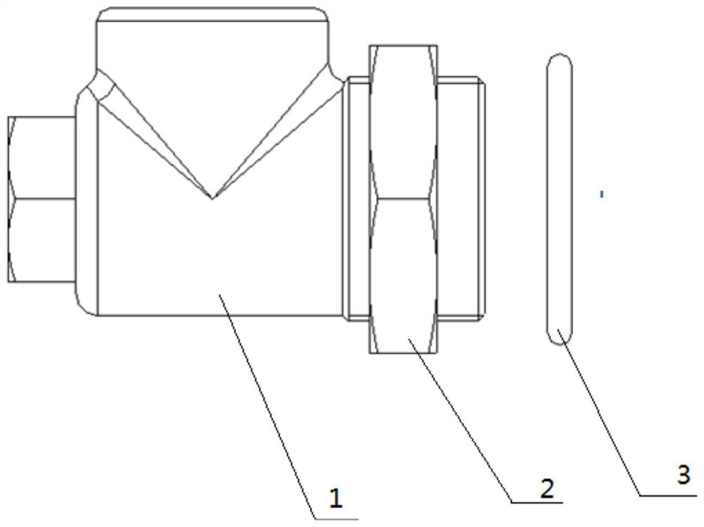
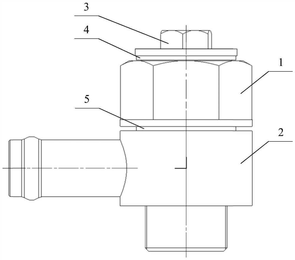
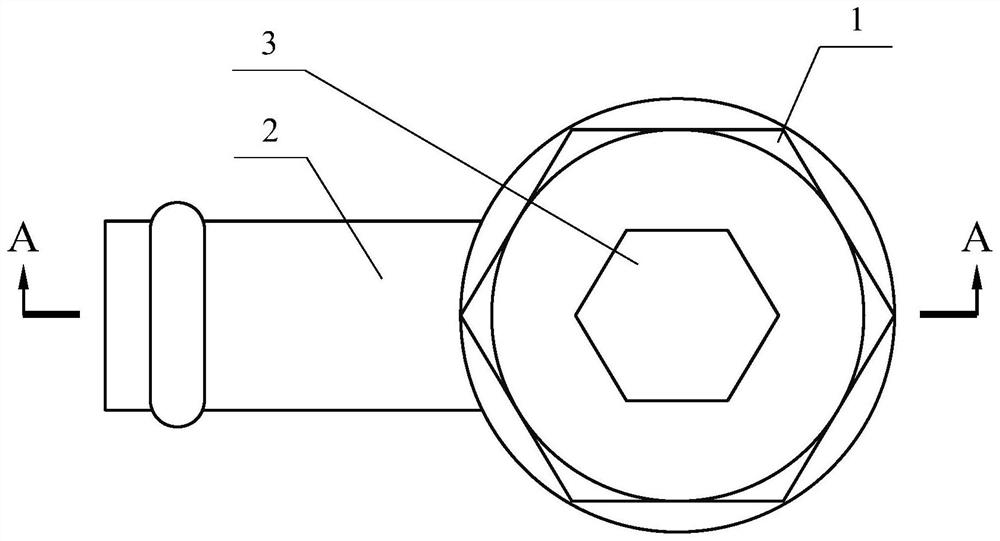
[0031]Such asFigure 2 to Figure 4As shown, an adjustable multifunctional combined joint structure according to a preferred embodiment of the present invention mainly includes a main transition joint 1, a connecting joint 2, a plug 3, a first combined gasket 4, and a second combined gasket 5. The main transition joint 1 includes a thin nut body 11 and a transition body 12. The transition body 12 has a cylindrical structure. The thin nut body 11 and the transition body 12 are coaxially connected. The thin nut body 11 includes an internal thread 13. The connecting joint 2 includes a connecting body 21 and a connecting head 22. The connecting head 22 is connected to the connecting body 21 along the radial direction of the connecting body 21. The connecting body 21 includes a transition hole 211. The transition body 12 is inserted in the transition hole 211 and the connecting joint 2 It can rotate 360 degrees with the transition body 12 as the axis. The internal thread 13 can be used to connect with other components or be blocked by a plug 3. The connector 22 can be used to connect heating pipes or other pipes.
[0032]Such asFigure 5 As shown, in some embodiments, the main transition joint 1 further includes at least one through hole group 14 disposed on the transition body 12, and the at least one through hole group 14 is communicated with the interior of the transition body 12. The number of through holes in at least one through hole group 14 is at least two, in other words, the number of through holes in each group can also be three or four. The central axes of at least two through holes are perpendicular to the central axis of the transition body 12 and intersect at one point at the same time. In other words, the central axes of each group of through holes are on the same plane.
[0033]SeeFigure 5 As shown, in some embodiments, the number of at least one through hole group 14 may also be two groups. The through holes of the two through hole groups 14 are alternately arranged along the central axis of the transition body 12, and the intersection of the through holes of the two through hole groups 14 and the central axis of the transition body 12 is along the transition body 12. Do not overlap in the radial direction. This design can increase the amount of liquid passing through the combined joint structure, and the two sets of through holes are separated by a certain distance from the top and bottom to prevent the transition body 12 from being weakened too much due to the setting of the through hole group 14, thereby affecting the locking Torque and sealing effect.
[0034]SeeFigure 5 As shown, in some embodiments, the thin nut body 11 and the connecting body 21 both include an upper plane and a lower plane, and the upper and lower planes of the thin nut body 11 and the upper and lower planes of the connecting body 21 are smooth mating surfaces. .
[0035]SeeFigure 5 As shown, in some embodiments, the main transition joint 1 further includes an external thread 15 provided at an end of the transition body 12 away from the thin nut body 11, and the external thread 15 can be used for connection of an engine or connection with other components. The external thread 15 can ensure the sealing effect by adding a combined sealing gasket on the mating surface of the engine or other components and the lower plane bracket of the connecting body 21.
[0036]Such asFigure 2 to Figure 4As shown, in some embodiments, the connecting joint 2 further includes a rib 221 disposed at the end of the connector 22 away from the connecting body 21. The rib 221 can be better equipped with a hose clamp and other locking parts to ensure connection with the hose. The sealing effect at the time. The protruding rib 221 can be provided with multiple channels, and this embodiment only shows one, but the present invention is not limited to this.
[0037]SeeFigure 2 to Figure 4As shown, in some embodiments, the adjustable multifunctional combined joint structure further includes a plug 3 which is screw-locked in the internal thread 13 of the main transition joint 1. The plug 3 includes an outer hexagon, a flange body and a stud. The outer hexagon is arranged on the upper part of the plug 3. The flange body is coaxially connected with the outer hexagon; the stud is coaxially connected with the flange body, and the stud is used to connect with the internal thread 13 of the thin nut body 11. The diameter of the flange body is larger than the diameter of the stud, and the lower surface of the flange body is a smooth mating surface.
[0038]SeeFigure 2 to Figure 4As shown, in some embodiments, the adjustable multifunctional combined joint structure further includes a first combined gasket 4 and a second combined gasket 5. The first combined gasket 4 is arranged between the lower plane of the flange body of the plug 3 and the upper plane of the thin nut body 11; the second combined gasket 5 is provided on the lower plane of the thin nut body 11 of the plug 3 and the connecting body 21 Between the upper planes. The first combined gasket 4 and the second combined gasket 5 can ensure the sealing effect of the combined joint structure after the internal thread 13 is locked with the engine or other components by rotating the thin nut body 11.
[0039]In some embodiments, the method of using the adjustable multifunctional combined joint structure of the present invention is as follows: firstly, cover the combined gasket on the transition body 12 of the main transition joint 1, and then pass the transition body 12 through the connecting body 21 Transition hole 211, and then put a combined seal on the part of transition body 12 passing through transition hole 211, connect the external thread 15 on the transition body 12 with the internal thread 13 of the engine or other parts, and adjust the connection head of the connection joint 2. 22 to make it suitable for connection with other connecting pipelines, and lock the thin nut body 11 until the two combined gaskets are compressed and sealed. Use hose clamp parts to lock the connecting head 22 to connect with other closed hoses. If the internal thread 13 on the thin nut body 11 is temporarily not used for connection with other components, a combined gasket can be put on the stud of the plug 3, and then the stud is tightened into the internal thread 13, and finally the plug 3 is rotated The outer six sides make the plug 3 lock tight.
[0040]In summary, the adjustable multifunctional combined joint structure of the present invention has the following advantages: it can realize the 360° direction of the pipeline joints can be adjusted at will, reserved ports, and sealed with composite gaskets; it can be applied to multiple pipelines The need for connection will not cause edge trimming of the O-ring, which can guarantee the locking torque and ensure the reliability of the seal. The direction of the heating water connector can be adjusted arbitrarily, which makes it easier to arrange the water pipeline of the whole vehicle, which is suitable for different models; integrates multiple interfaces, which can meet the water intake requirements of multiple water pipes of different interface forms at the same time, and adapt to the increasing water intake requirements of the vehicle; integrated lock The form of tightening nut and pressing washer makes the tightening torque simple and convenient, easy to process and manufacture, and low cost.
[0041]The foregoing description of specific exemplary embodiments of the present invention is for the purpose of illustration and illustration. These descriptions are not intended to limit the invention to the precise form disclosed, and it is obvious that many changes and changes can be made based on the above teachings. The purpose of selecting and describing the exemplary embodiments is to explain the specific principles of the present invention and its practical application, so that those skilled in the art can realize and use various exemplary embodiments of the present invention and various different Choice and change. The scope of the present invention is intended to be defined by the claims and their equivalents.