Rigidity-controllable supporting device and CT machine frame system

A support device and rigidity technology, applied in the field of devices that can control the support rigidity, can solve the problems of the influence of the support effect, the complex structure, the difficulty of steplessly adjusting the angle of the frame, etc., and achieve the effect of ensuring safe operation and improving the rigidity of the support.

Pending Publication Date: 2021-02-12
苏州波影医疗技术有限公司
View PDF10 Cites 0 Cited by
  • Summary
  • Abstract
  • Description
  • Claims
  • Application Information

AI Technical Summary

Problems solved by technology

Using a purely mechanical support structure to achieve the above functions, the structure is complex, it is difficult to adjust the angle of the rack steplessly, and the support effect is easily affected due to wear and tear of structural parts

Method used


Image

  • Rigidity-controllable supporting device and CT machine frame system
  • Rigidity-controllable supporting device and CT machine frame system
  • Rigidity-controllable supporting device and CT machine frame system

Examples


Embodiment 1

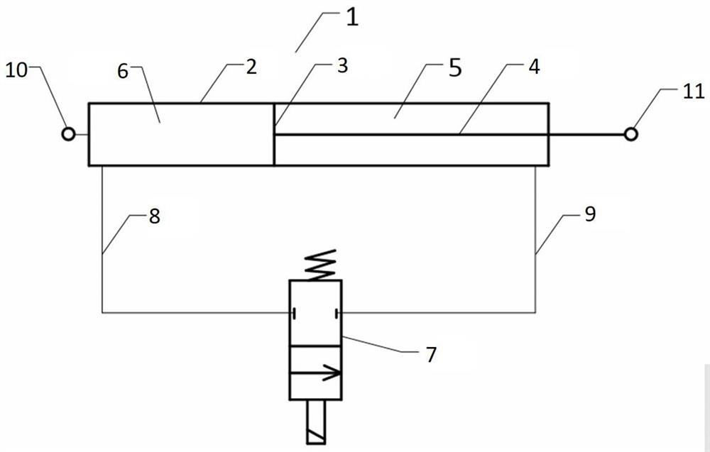
[0025]Example 1: See attachedfigure 1 As shown, a support device with controllable stiffness includes an oil cylinder 1. The oil cylinder 1 is composed of a cylinder barrel 2, a piston 3 and a piston rod 4. The inside of the cylinder barrel 2 is divided into a rod cavity 5 and a rodless cavity 6 by the piston 3 In two parts, the outer end of the cylinder at one end of the rodless cavity 6 is fixedly connected with an earring as the first connecting structure 10, and the outer end of the piston rod 4 is fixedly connected with an earring as the second connecting structure 11.

[0026]A solenoid valve 7 is provided. The first oil port of the solenoid valve 7 communicates with the rodless cavity 6 through the first pipe 8, and the second oil port of the solenoid valve 7 communicates with the rod cavity 5 through the second pipe 9. The oil port and the second oil port are controlled by the solenoid valve 7. The rod cavity 5, the rodless cavity 6, the first pipe 8 and the second pipe 9 are f...

Embodiment 2

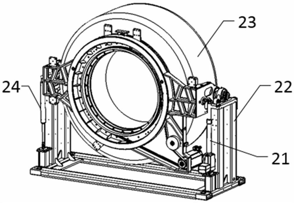
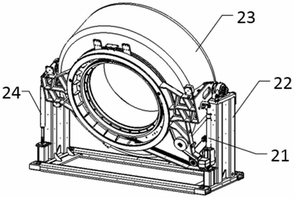
[0029]Example 2: See attachedfigure 2 As shown, a medical CT machine frame system is composed of a base 22, a tiltable part 23, a driving part 21, and a support device 24 with controllable stiffness. Wherein, the tiltable part 23 is rotatably connected to the base 22.

[0030]SeeFigure 4The driving component 21 in this embodiment adopts a hydraulic transmission mechanism to drive the tiltable part 23 to rotate relative to the base to adjust its tilt angle. A support device 24 with controllable rigidity is provided at the other end of the frame for lifting the tiltable part. To support.

[0031]See attachedfigure 2 Andimage 3 , The frame needs to have different postures when working, the driving part 21 is used to change the frame posture, and the rigidity controllable support device 24 is used to lock the frame when the frame reaches the working posture to increase the frame rigidity.

[0032]Typical system block diagram such asFigure 4As shown, the rigidity controllable support device 24 an...


PUM


Abstract

The invention discloses a rigidity-controllable supporting device and a CT machine frame system, the supporting device comprises an oil cylinder, the oil cylinder is composed of a cylinder barrel, a piston and a piston rod, the interior of the cylinder barrel is divided into a rod cavity and a rodless cavity by means of the piston and is characterized in that a valve is arranged, two connecting openings of the valve are in communication with the rodless cavity and the rod cavity through a first pipeline and a second pipeline respectively, connection and disconnection between the two connectingopenings are controlled by the valve, the rod cavity, the rodless cavity, the first pipeline and the second pipeline are filled with fluid media, the cylinder barrel and the piston rod are used as two supporting parts of the supporting device, and the rigidity of the supporting device is changed by adjusting connection and disconnection of the valve. The CT machine frame system comprises a base,an inclinable part and a driving part, and at least one rigidity-controllable supporting device is arranged between the base and the inclinable part. According to the rigidity-controllable supportingdevice and the CT machine frame system, the rigidity of the supporting device is controllable, and the supporting device can be used for supporting equipment with the pose needing to be changed.

Description

Technical field[0001]The invention relates to a support device, in particular to a device that can control the support stiffness, in particular to a device that can realize automatic switching of the support stiffness through control.Background technique[0002]Commonly used supporting devices, especially those suitable for supporting various equipment, usually have inherent stiffness coefficients, and it is difficult to change their supporting stiffness through external control.[0003]Some devices need to switch their poses when they are working, especially some large-span, low-rigidity devices that need to maintain the current pose with higher rigidity after reaching the target pose. For example, in the rack system of a medical CT machine, a tiltable part is set in the rack according to the requirements of the application scenario. When the tilt angle position is reached, a good rigid support is required to avoid occurrence during the detection process. Vibration, deviation, etc. The...

Claims


Application Information

Patent Timeline
Patent Type & Authority Applications(China)
IPC IPC(8): F16M11/04F16M11/18
CPCF16M11/043F16M11/18
Inventor 刘岿陆泉望杨理
Owner 苏州波影医疗技术有限公司
Why Eureka
Try Eureka