
Shock absorber and engine system

A technology of shock absorbing device and rubber shock absorbing block, applied in the directions of engine components, machines/engines, springs/shock absorbers, etc., can solve the problems of small working angle, unstable quality, poor control of stiffness, etc., to restrain torsion Good vibration, shock absorption and simple structure

Active Publication Date: 2021-07-09
SHANTUI CONSTR MASCH CO LTD
View PDF8 Cites 0 Cited by
  • Summary
  • Abstract
  • Description
  • Claims
  • Application Information

AI Technical Summary

Problems solved by technology

However, the working environment of bulldozers is relatively complicated, mostly in mines, coal yards and water conservancy projects. Sometimes the shock and vibration generated by the engine will be very large. Due to the limitation of the structure of the spring shock absorber itself, for example, the torsional stiffness of the spring is relatively large, and the stiffness is not high. Good control, the spring stiffness produced is poor in consistency, the quality is extremely unstable, and the working angle is small, which cannot effectively avoid the resonance zone of the whole machine, which seriously affects the performance of the bulldozer

Method used


Image

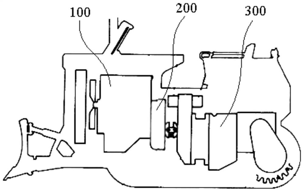
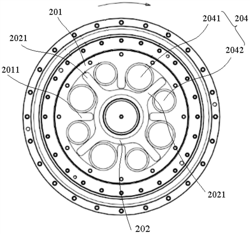
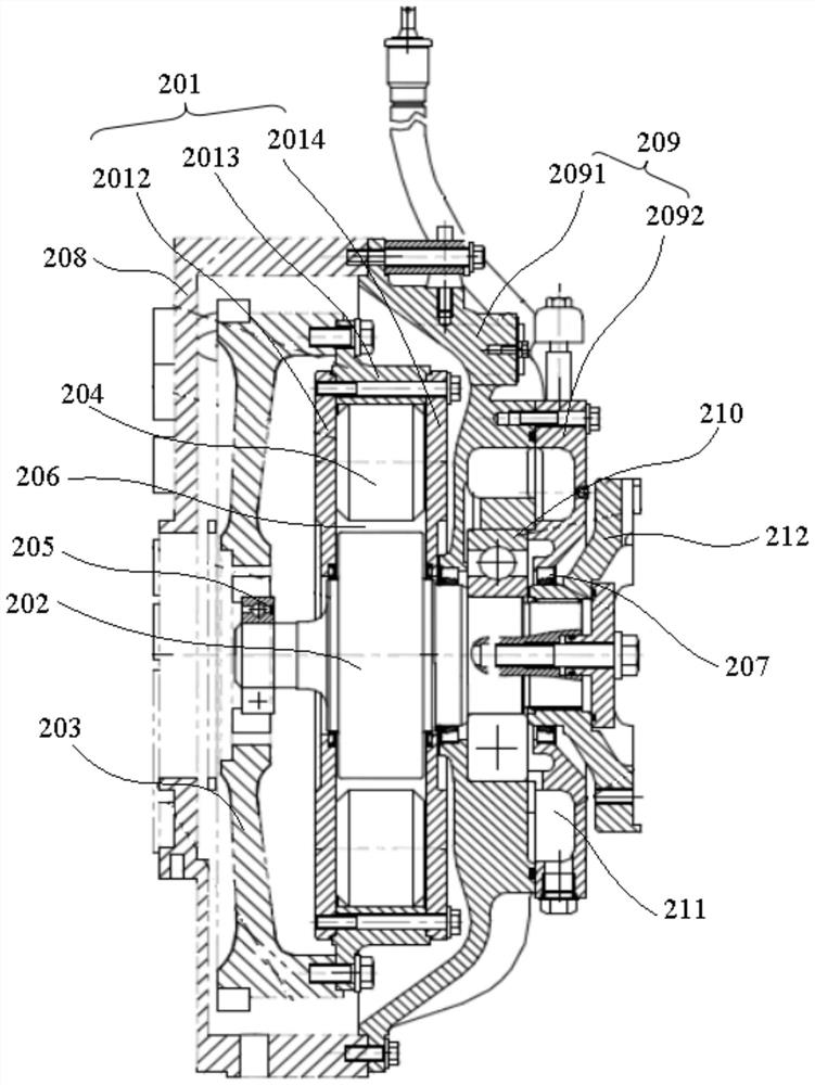
  • Shock absorber and engine system
  • Shock absorber and engine system
  • Shock absorber and engine system

Examples


Embodiment Construction

[0033] The technical solutions of the present invention will be further described below in conjunction with the accompanying drawings and through specific implementation methods.

[0034] In describing the present invention, it is to be understood that the terms "upper", "lower", "front", "rear", "left", "right", "vertical", "horizontal", "top", The orientation or positional relationship indicated by "bottom", "inner", "outer", etc. is based on the orientation or positional relationship shown in the drawings, and is only for the convenience of describing the present invention and simplifying the description, rather than indicating or implying the referred device Or elements must have a certain orientation, be constructed and operate in a certain orientation, and thus should not be construed as limiting the invention. The terms "first", "second", "third" and the like are only used for distinguishing descriptions, and should not be construed as indicating or implying relative im...


PUM


Abstract

The invention discloses a damping device and an engine system, belonging to the technical field of damping. The shock absorbing device of the present invention includes a casing and a transmission shaft, the casing is used to connect with the rotating drive and the inner wall of the casing is provided with a plurality of internal convex teeth along the circumference; the transmission shaft is passed through the casing, and the outer wall of the transmission shaft is A plurality of outer convex teeth are arranged in the direction, and the outer convex teeth and the inner convex teeth are alternately distributed, and rubber shock absorbers are arranged between the adjacent outer convex teeth and the inner convex teeth. When the flywheel drives the casing to rotate, the inner convex teeth on the casing turn the drive shaft through the rubber shock absorber, and the drive shaft drives the subsequent transmission system to rotate. The elastic damping of the rubber shock absorber can change the rigid impact into elastic impact, Realize shock absorption; and the stiffness of the rubber shock absorber is easy to control, and the stiffness of the rubber shock absorber is smaller, which can more effectively consume the vibration energy in the form of heat energy, thereby suppressing torsional vibration and avoiding the vibration of the whole machine to the greatest extent. Natural frequency, good shock absorption effect.

Description

technical field [0001] The invention relates to the technical field of engine damping, in particular to a damping device and an engine system. Background technique [0002] At present, most engineering vehicles are driven by internal combustion engines. During the working process of the engine, the elasticity of the crankshaft and the periodic torque acting on the shafting make the engine always have torsional vibration. Torsional vibration will cause the shaft system to bear alternating stress. With the accumulation of fatigue, it will cause sudden fracture of the crankshaft, transmission system shaft, bolts, gears, etc.; The noise will aggravate the wear of other parts, and even serious damage accidents such as breakage of transmission system parts will occur. [0003] Installing the torsional shock absorber can adjust the torsional natural vibration frequency of the crankshaft without changing the structure, moment of inertia and stiffness of other transmission systems, ...

Claims


Application Information

Patent Timeline
Patent Type & Authority Patents(China)
IPC IPC(8): F16F15/136F02B77/00
CPCF02B77/00F16F15/136F16F2230/04F16F15/1245
Inventor 吕克明张明月杜晓萍冯西友胡凯李东浪金丹
Owner SHANTUI CONSTR MASCH CO LTD
Learn More