Eureka AIR delivers breakthrough ideas for toughest innovation challenges, trusted by R&D personnel around the world.

A multi-stage energy dissipation device for earthquake resistance and vibration reduction of building structures

A technology for building structures and energy-consuming devices, applied in building components, buildings, building types, etc.

Active Publication Date: 2021-09-14
XIAN UNIV OF SCI & TECH
View PDF5 Cites 0 Cited by
  • Summary
  • Abstract
  • Description
  • Claims
  • Application Information

AI Technical Summary

Problems solved by technology

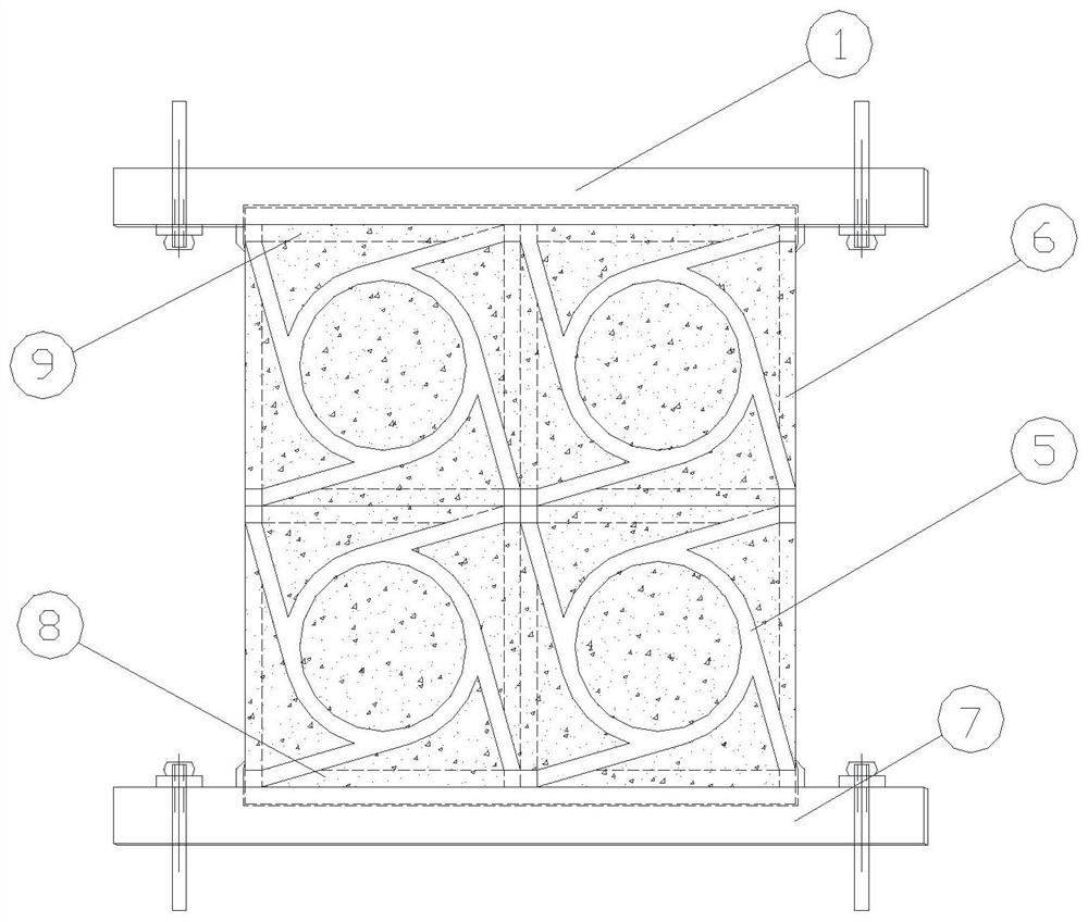
[0004] In order to solve the problem of engineering structures in terms of anti-vibration and implement multi-stage energy consumption performance, the present invention proposes a multi-stage energy consumption device for anti-seismic and vibration reduction of building structures

Method used


Image

  • A multi-stage energy dissipation device for earthquake resistance and vibration reduction of building structures
  • A multi-stage energy dissipation device for earthquake resistance and vibration reduction of building structures
  • A multi-stage energy dissipation device for earthquake resistance and vibration reduction of building structures

Examples


Embodiment 1

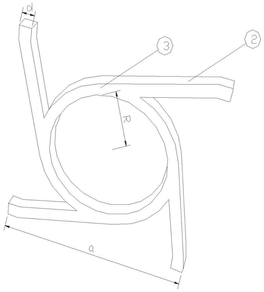
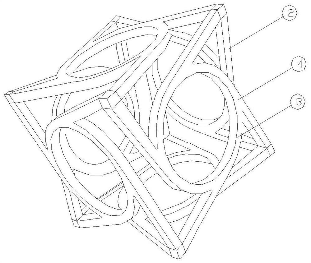
[0023] Such as figure 1 , 2 , shown in 3 and 4, a multi-stage energy dissipation device for anti-seismic and vibration reduction of a building structure, including a base (7), a skeleton unit (5) and a support plate (1), is characterized in that: a plurality of said skeleton units (5) form a steel skeleton, the lower part of the steel skeleton is provided with a base (7), the skeleton unit (5) is composed of six plates (4) of the same form, and the inside of the plate is a ring (3), Four equal support rods (2) protrude tangentially at equal intervals from the outside, the inside of the skeleton unit (5) is filled with high damping rubber (6), and a support plate (1) is arranged on the upper part of the steel skeleton.

[0024] The upper surface of the base (7) is provided with an upper groove (8), the steel frame is placed in the upper groove (8), and the base (7) is welded under the steel frame.

[0025] The lower surface of the support plate (1) is provided with a lower gr...

Embodiment 2

[0033] Rigidity adjustment and programming control can be realized by adjusting the internal and external radius and thickness of the inner ring (3) of the plate (4), the size of the included angle of the support rod (2) and the number of skeleton units (5).

[0034] When the outer steel skeleton is subjected to axial pressure, the skeleton unit (5) will be torsionally deformed, reflecting the compression-torsion coupling effect. Such as Figure 5 , 6 As shown, the stiffness of the system is designed by adjusting parameters such as the radius, width, and unit cell size of the ring to achieve controllable stiffness.

[0035] The data simulation analysis of the energy-consuming device is carried out. Due to the periodic characteristics of the system, a skeleton unit (5) of the device is used for pseudo-static numerical analysis. The lower part of the skeleton unit (5) is fixed, and the axial cyclic displacement is applied to the upper part of the skeleton unit (5) through disp...


PUM


Abstract

The invention discloses a multi-stage energy consumption device for anti-seismic and vibration reduction of a building structure, which includes a base, a skeleton unit and a support plate, and is characterized in that: the steel skeleton of the device is composed of the several skeleton units, and the skeleton unit is composed of Composed of six plates of the same form, the interior of the plates is composed of rings, and four equal support rods protrude tangentially at equal intervals from the outside. The interior of the skeleton is filled with high-damping rubber, and the upper part of the steel skeleton is covered with a support plate. The device utilizes the composite properties of negative Poisson's ratio steel skeleton and high damping rubber. It is a vibration isolation and anti-seismic system with adjustable damping. Its stiffness can be controlled and damping can be adjusted, which is convenient for multi-level energy consumption design according to the dynamic performance of the structure. .

Description

technical field [0001] The invention relates to the field of structure vibration control, in particular to a multi-stage energy consumption device for anti-seismic and vibration-reduction of building structures. Background technique [0002] Structural vibration has gradually become a key issue in the structural design of bridges, industrial and civil buildings. Traffic loads generate vertical vibrations on bridge structures, and seismic loads generate horizontal vibrations in building structures, which can lead to premature damage and collapse of structures. Seismic loads, in particular, are unpredictable. my country's "Detailed Rules for Seismic Design of Highway Bridges" divides design earthquakes into two grades: E1 earthquakes with a short return period on the engineering site and E2 earthquakes with a long return period on the engineering site; The aseismic design principle of classified fortifications that can be repaired and will not collapse after a large earthquak...

Claims


Application Information

Patent Timeline
Patent Type & Authority Patents(China)
IPC IPC(8): E01D19/00E04B1/98E04H9/02
CPCE01D19/00E04B1/98E04H9/021
Inventor 刘群峰朱诗敏郭朝阳李箫霆杨雅茗
Owner XIAN UNIV OF SCI & TECH
Why Eureka
Eureka Blog
Learn More