Machine element clamping equipment with cutting function

A technology of mechanical parts and clamping equipment, which is applied in the field of mechanical processing, can solve problems such as steel pipe scratches, flattening, and affecting quality, and achieve the effects of easy cutting, reduced manual pressure, and strong adaptability of the device

Inactive Publication Date: 2021-02-19
YANTAI ENG & TECH COLLEGE YANTAI TECHNICIAN INST
View PDF0 Cites 0 Cited by
  • Summary
  • Abstract
  • Description
  • Claims
  • Application Information

AI Technical Summary

Problems solved by technology

Such upper and lower clamping devices, if the height of the fixed position of the lower clamping block is higher than the bottom surface of the steel pipe, the steel pipe will rub hard on the clamping block, and the steel pipe will be seriously scratched. If the fixing block is lower than the bottom surface of the steel pipe, Leave a certain gap, when the upper clamping block is clamped downward, the steel pipe will clamp the section, and it will be flattened, which will seriously affect the quality

Method used


Image

  • Machine element clamping equipment with cutting function
  • Machine element clamping equipment with cutting function
  • Machine element clamping equipment with cutting function

Examples


Embodiment 1

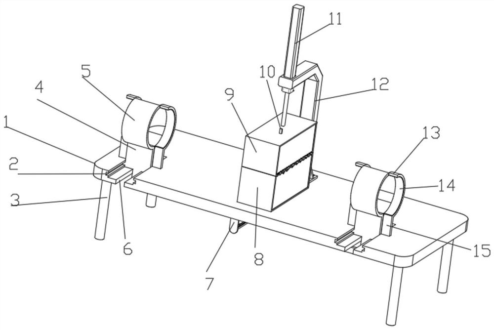
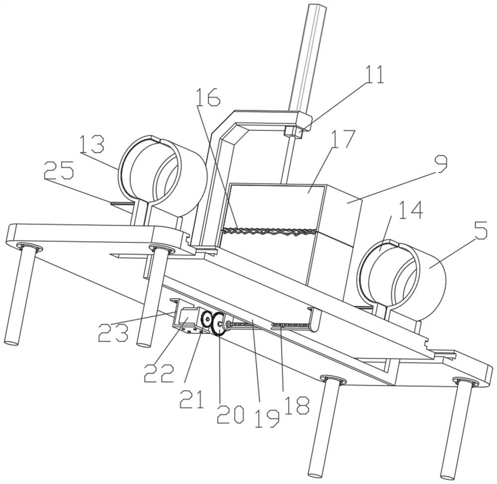
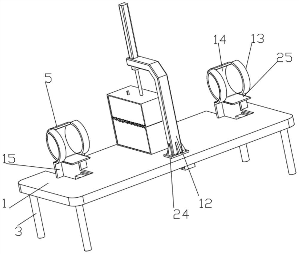
[0033] Such as Figure 1-5A clamping device for mechanical parts with a cutting function is shown, including a workbench 1 and a cylinder 11. The bottom of the workbench 1 is symmetrically fixedly connected with outriggers 3, and the workbench 1 is connected with a fixed structure for fixing parts. The fixed structure includes Cross chute 2, cross slide 4, middle arc splint 5, outer arc splint 13, connecting plate 15, threaded rod 18, driven ring gear 20, rotating motor 22 and Z-shaped support plate 23, Z-shaped support plate 23 The top of the top is fixedly connected with the bottom of the workbench 1, the Z-shaped support plate 23 is fixedly installed with a rotating motor 22, the output end of the rotating motor 22 is fixedly connected with a driving ring gear 21, and the driving ring gear 21 is meshed with a driven ring gear 20, The driven ring gear 20 is fixedly connected with a threaded rod 18, the threaded rod 18 is threadedly connected with a U-shaped plate 19, the top...

Embodiment 2

[0035] Such as Figure 1-5 A clamping device for mechanical parts with a cutting function is shown, including a workbench 1 and a cylinder 11. The bottom of the workbench 1 is symmetrically fixedly connected with outriggers 3, and the workbench 1 is connected with a fixed structure for fixing parts. The fixed structure Including cross chute 2, cross slide 4, middle arc splint 5, outer arc splint 13, connecting plate 15, threaded rod 18, driven ring gear 20, rotating motor 22 and Z-shaped support plate 23, Z-shaped support plate 23 is fixedly installed with a rotating motor 22, the output end of the rotating motor 22 is fixedly connected with a driving ring gear 21, and the driving ring gear 21 is meshed with a driven ring gear 20, and the driven ring gear 20 is fixedly connected with a threaded rod 18, and the threaded rod 18 A U-shaped plate 19 is threadedly connected, and cross slides 4 are fixedly connected to both ends of the top of the U-shaped plate 19. The top of the cr...

Embodiment 3

[0037] Embodiment 3 is a further improvement to Embodiment 1.

[0038] Such as Figure 1-5 A clamping device for mechanical parts with a cutting function is shown, including a workbench 1 and a cylinder 11. The bottom of the workbench 1 is symmetrically fixedly connected with outriggers 3, and the workbench 1 is connected with a fixed structure for fixing parts. The fixed structure Including cross chute 2, cross slide 4, middle arc splint 5, outer arc splint 13, connecting plate 15, threaded rod 18, driven ring gear 20, rotating motor 22 and Z-shaped support plate 23, Z-shaped support plate 23 is fixedly installed with a rotating motor 22, the output end of the rotating motor 22 is fixedly connected with a driving ring gear 21, and the driving ring gear 21 is meshed with a driven ring gear 20, and the driven ring gear 20 is fixedly connected with a threaded rod 18, and the threaded rod 18 A U-shaped plate 19 is threadedly connected, and cross slides 4 are fixedly connected to...


PUM


Abstract

The invention relates to the field of machining, in particular to machine element clamping equipment with a cutting function. The clamping equipment comprises a workbench, wherein the workbench is provided with a fixing structure; the fixing structure comprises a cross-shaped sliding groove, a cross-shaped sliding plate, a middle arc-shaped clamping plate, an outer side arc-shaped clamping plate,a connecting plate, a threaded rod, a driven gear ring, a rotating motor and a Z-shaped supporting plate, wherein the Z-shaped supporting plate is provided with the rotating motor, the rotating motoris provided with a driving gear ring, the driving gear ring is provided with the driven gear ring, the driven gear ring is provided with the threaded rod, the threaded rod is provided with a U-shapedplate, the U-shaped plate is provided with the cross-shaped sliding plate, and the cross-shaped sliding plate is provided with the middle arc-shaped clamping plate; and the workbench is provided withthe connecting plate, the connecting plate is provided with the outer side arc-shaped clamping plate which is attached to the side wall of the middle arc-shaped clamping plate and is slidably connected with the same, the workbench is provided with the cross-shaped sliding groove, and the workbench is provided with a mounting bottom plate; and the mounting bottom plate is provided with a supportingframe, the supporting frame is provided with an air cylinder, the air cylinder is provided with a mounting frame, the mounting frame is provided with a driving motor, and the driving motor is provided with a cutting disc. According to the equipment, a pipe of a machine element can be conveniently fixed, and cutting is facilitated.

Description

technical field [0001] The invention relates to the field of mechanical processing, in particular to a mechanical part clamping device with a cutting function. Background technique [0002] Machine element, also known as machine part, is the basic element of machinery, and it is an inseparable single part that makes up machinery and machines. Mechanical parts are not only a subject of research and design of mechanical basic parts in various equipment, but also a general term for parts and components. When machining mechanical parts, a cutting machine is required for cutting. [0003] Cutting machine is divided into flame cutting machine, plasma cutting machine, laser cutting machine, water cutting and so on. The laser cutting machine has the fastest efficiency, the highest cutting precision, and the cutting thickness is generally small. The cutting speed of the plasma cutting machine is also very fast, and the cutting surface has a certain slope. The flame cutting machin...

Claims


Application Information

Patent Timeline
IPC IPC(8): B23D45/12B23D47/04B23D59/00
CPCB23D45/12B23D47/04B23D59/006
Inventor 张燕
Owner YANTAI ENG & TECH COLLEGE YANTAI TECHNICIAN INST
Why Eureka
Try Eureka