Plastic square piece block mark branding equipment
A branding and block technology, which is applied in the field of branding equipment for plastic square signs, to achieve the effects of strong equipment work continuity, reduced labor intensity, and improved branding efficiency
- Summary
- Abstract
- Description
- Claims
- Application Information
AI Technical Summary
Problems solved by technology
Method used
Image
Examples
Embodiment 1
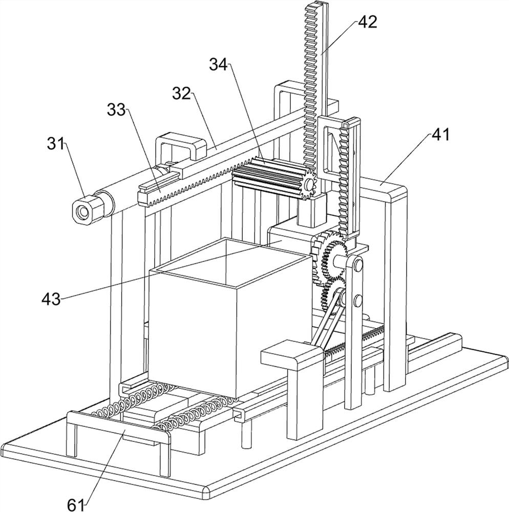
[0025] A plastic square block logo branding equipment, such as figure 1 , figure 2 and Figure 4 As shown, it includes a base plate 1, a support frame 2, a drive mechanism 3, a branding mechanism 4 and a card seat mechanism 5. Two support frames 2 are connected to the top rear side of the base plate 1, and a support is connected to the left rear side of the top of the base plate 1. The support and A driving mechanism 3 is installed between the support frames 2, a branding mechanism 4 is installed on the top of the bottom plate 1, and the branding mechanism 4 is connected to the driving mechanism 3 by transmission, and a card holder mechanism 5 is installed on the top of the bottom plate 1.
[0026] The driving mechanism 3 includes a cylinder 31, a first rail frame 32, a first sliding rack bar 33 and a first gear 34, the cylinder 31 is installed on the left side of the top of the bracket, and the first rail frame is connected between the tops of the two support frames 2. 32....
Embodiment 2
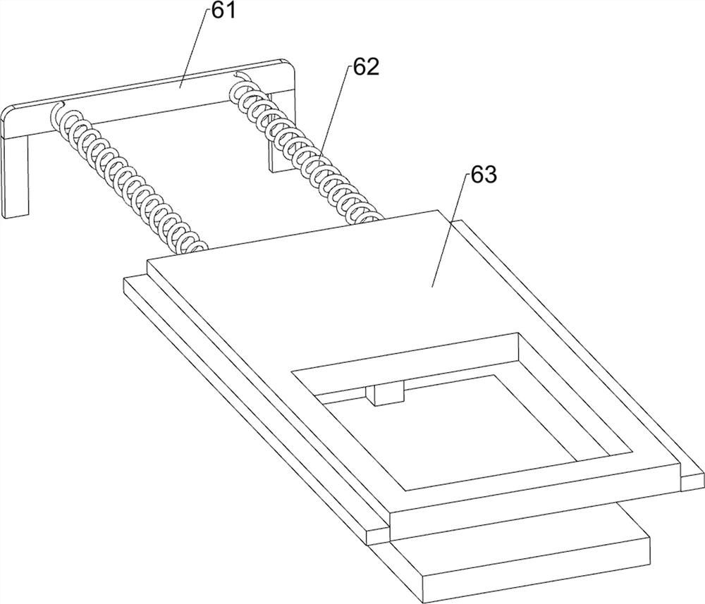
[0031] On the basis of Example 1, such as image 3 and Figure 5 As shown, a feeding mechanism 6 is also included. The feeding mechanism 6 includes a fixed plate 61, a second return spring 62, a pushing plate 63 and a third guide rail frame 64. The left side of the top of the bottom plate 1 is connected with the fixed plate 61. The front and rear sides of the front and rear sides are all connected with a third guide rail frame 64, and a pusher plate 63 is slidably connected between the two third guide rail frames 64. The pusher plate 63 is slidably matched with the base frame 51, and the pusher plate 63 is connected with the fixed plate 61. There are two second return springs 62 connected front and back symmetrically.
[0032] When the plastic square piece 9 was branded, the plastic square piece 9 was positioned on the pushing plate 63. After a plastic square piece 9 was branded, the pushing plate 63 could be manually moved to the left, and the second return spring 62 followe...
Embodiment 3
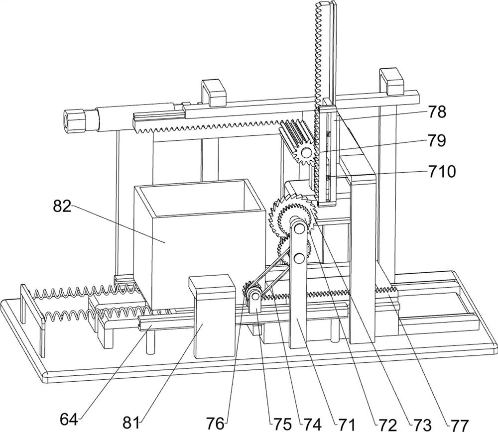
[0034] On the basis of Example 2, such as image 3 As shown, a linkage mechanism 7 is also included, and the linkage mechanism 7 includes a mounting frame 71, an opposing gear set 72, a ratchet gear 73, a transmission belt set 74, a mounting seat 75, a second gear 76, a rack plate 77, and a connecting frame 78. Movable straight gear rod 79 and the third back-moving spring 710, base plate 1 top front side is connected with mounting frame 71, is connected with opposing gear set 72 in rotation on mounting frame 71, is connected with the transmission shaft of opposing gear set 72 Ratchet gear 73, the top of the third guide rail frame 64 on the front side is connected with mounting seat 75, and the mounting seat 75 is connected with the second gear 76 in rotation, between the transmission shaft of the second gear 76 and the transmission shaft of the opposite gear set 72 A transmission belt group 74 is connected, a rack plate 77 is connected to the front side of the top of the pushi...
PUM
 Abstract
Description
Claims
Application Information
 - R&D
- Intellectual Property
- Life Sciences
- Materials
- Tech Scout
- Unparalleled Data Quality
- Higher Quality Content
- 60% Fewer Hallucinations
Browse by: Latest US Patents, China's latest patents, Technical Efficacy Thesaurus, Application Domain, Technology Topic, Popular Technical Reports.
© 2025 PatSnap. All rights reserved.Legal|Privacy policy|Modern Slavery Act Transparency Statement|Sitemap|About US| Contact US: help@patsnap.com


