Hydraulic engineering construction diversion drainage structure and construction method thereof

A technology for construction of diversion and drainage structures, applied in waterway systems, water supply devices, sewer systems, etc., can solve problems such as difficult positioning, protection of main transportation pipelines, long lengths, etc., to achieve convenient pipeline switching, avoid urban waterlogging, improve The effect of service life

Active Publication Date: 2021-02-19
祝珺 +4
View PDF7 Cites 0 Cited by
  • Summary
  • Abstract
  • Description
  • Claims
  • Application Information

AI Technical Summary

Problems solved by technology

[0002] During the construction of water conservancy projects, underground pre-buried pipelines are usually used to realize the centralized discharge of urban wastewater, but the pre-buried pipelines are deep and the maintenance costs are high, especially the main transportation pipeline, which is long in length and has many nodes. , difficult to locate
[0003] In the drainage process, due to the weather, there is a difference between the flood season and the non-flood season in the pipeline drainage. In the rainstorm weather, the water volume suddenly increases, the water flow in the pipeline increases, the impact force of the water flow and the mixture in the water increase. During transportation, due to the impact of the water flow and the inertia of the mixed sediment and stones in the water, it is very easy to cause extrusion on the inner wall of the pipeline, thereby reducing the practical life of the pipeline, and the water volume increases. The transportation of a single pipeline cannot meet the needs of excretion, which is easy cause waterlogging
[0004] To this end, a water conservancy construction diversion and drainage structure and its construction method are provided to solve the problem of switching pipelines between flood seasons and non-flood seasons and protecting the main transportation pipelines

Method used


Image

  • Hydraulic engineering construction diversion drainage structure and construction method thereof
  • Hydraulic engineering construction diversion drainage structure and construction method thereof
  • Hydraulic engineering construction diversion drainage structure and construction method thereof

Examples


Embodiment Construction

[0030] The following will clearly and completely describe the technical solutions in the embodiments of the present invention with reference to the accompanying drawings in the embodiments of the present invention. Obviously, the described embodiments are only some, not all, embodiments of the present invention. Based on the embodiments of the present invention, all other embodiments obtained by persons of ordinary skill in the art without making creative efforts belong to the protection scope of the present invention.

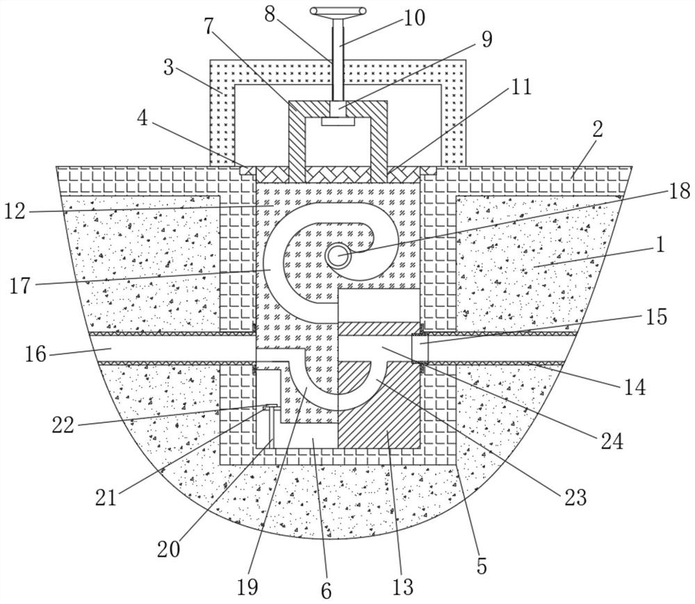
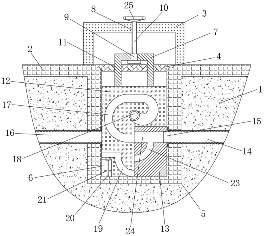
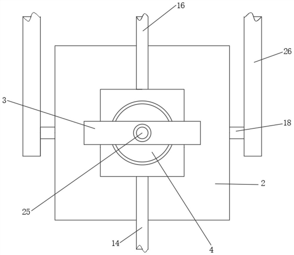
[0031] see Figure 1 to Figure 4 , the present invention provides a technical solution:

[0032] A diversion and drainage structure for water conservancy engineering construction, comprising a feed pipe 14 and a discharge pipe 16, the feed pipe 14 and the discharge pipe 16 are pre-buried and installed at the lower end of the foundation 1, and the feed pipe 14 and the discharge pipe 16 Vertically distributed deep holes 5 are arranged between them. The deep hol...


PUM


Abstract

The invention relates to the technical field of hydraulic engineering drainage construction, in particular to a hydraulic engineering construction diversion drainage structure and a construction method thereof. The hydraulic engineering construction diversion drainage structure comprises a feeding pipe and a discharging pipe; the feeding pipe and the discharging pipe are installed at the lower endof a foundation in a pre-buried mode; deep holes which are vertically distributed are formed between the feeding pipe and the discharging pipe; and flow dividing pipes are symmetrically arranged on the left side and the right side of the feeding pipe and the left side and the right side of the discharging pipe. The construction method of the hydraulic engineering construction division drainage structure comprises the following steps of S1, base pouring; S2, fixed block pouring; S3, lifting block pouring; and S4, lifting block adjusting. The structure and the method have the beneficial effectsthat by arranging a lifting block with a spiral upper and lower flow channels, high-speed impact water flow is buffered, the impact force of the water flow is reduced, meanwhile, the purpose of left-right flow division is achieved through up-down circulating flow of the water flow, damage to a main pipeline is avoided, and the service life of the main pipeline is prolonged.

Description

technical field [0001] The invention relates to the technical field of water conservancy project drainage construction, in particular to a water conservancy project construction diversion drainage structure and a construction method thereof. Background technique [0002] During the construction of water conservancy projects, underground pre-buried pipelines are usually used to realize the centralized discharge of urban wastewater, but the pre-buried pipelines are deep and the maintenance costs are high, especially the main transportation pipeline, which is long in length and has many nodes. , positioning is difficult. [0003] In the drainage process, due to the weather, there is a difference between the flood season and the non-flood season in the pipeline drainage. In the rainstorm weather, the water volume suddenly increases, the water flow in the pipeline increases, the impact force of the water flow and the mixture in the water increase. During transportation, due to t...

Claims


Application Information

Patent Timeline
Patent Type & Authority Applications(China)
IPC IPC(8): E03F3/04E03F3/06
CPCE03F3/04E03F3/06
Inventor 祝珺赵贞岩陈明张苹代东波
Owner 祝珺
Why Eureka
Try Eureka