Mechanical overload protection device
An overload protection, mechanical technology, applied in the direction of mechanical equipment, transmission devices, belts/chains/gears, etc., to achieve the effect of improving service life, reducing friction coefficient, and reducing friction loss
- Summary
- Abstract
- Description
- Claims
- Application Information
AI Technical Summary
Problems solved by technology
Method used
Image

Examples
Embodiment 1
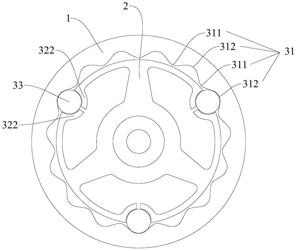
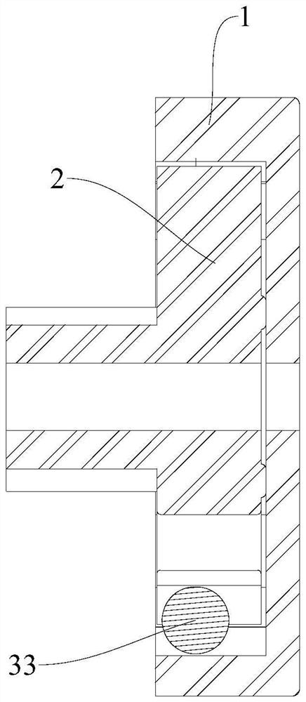
[0034] refer to Figure 1-2 , the mechanical overload protection device of the present invention includes: a first rotating part 1, a second rotating part 2 and an overload protection assembly; the second rotating part 2 is coaxially arranged inside the first rotating part 1; the overload protection assembly includes a wave track 31 , at least one elastic support part and rolling elements 33 equal in number to the elastic support part; the wave track 31 is arranged on the inside of the first rotating part 1, and the elastic support part is arranged on the outside of the second rotating part 2; the wave track 31 has a closed wave profile Surface, the corrugated profile surface includes crest surface 311 and trough surface 312 connected in sequence; the elastic support part has a groove that can be deformed along the direction away from the wave track 31; Between the grooves, the rolling body 33 is suitable for rotating around its own rotation axis 331 in the groove, and the rol...
Embodiment 2
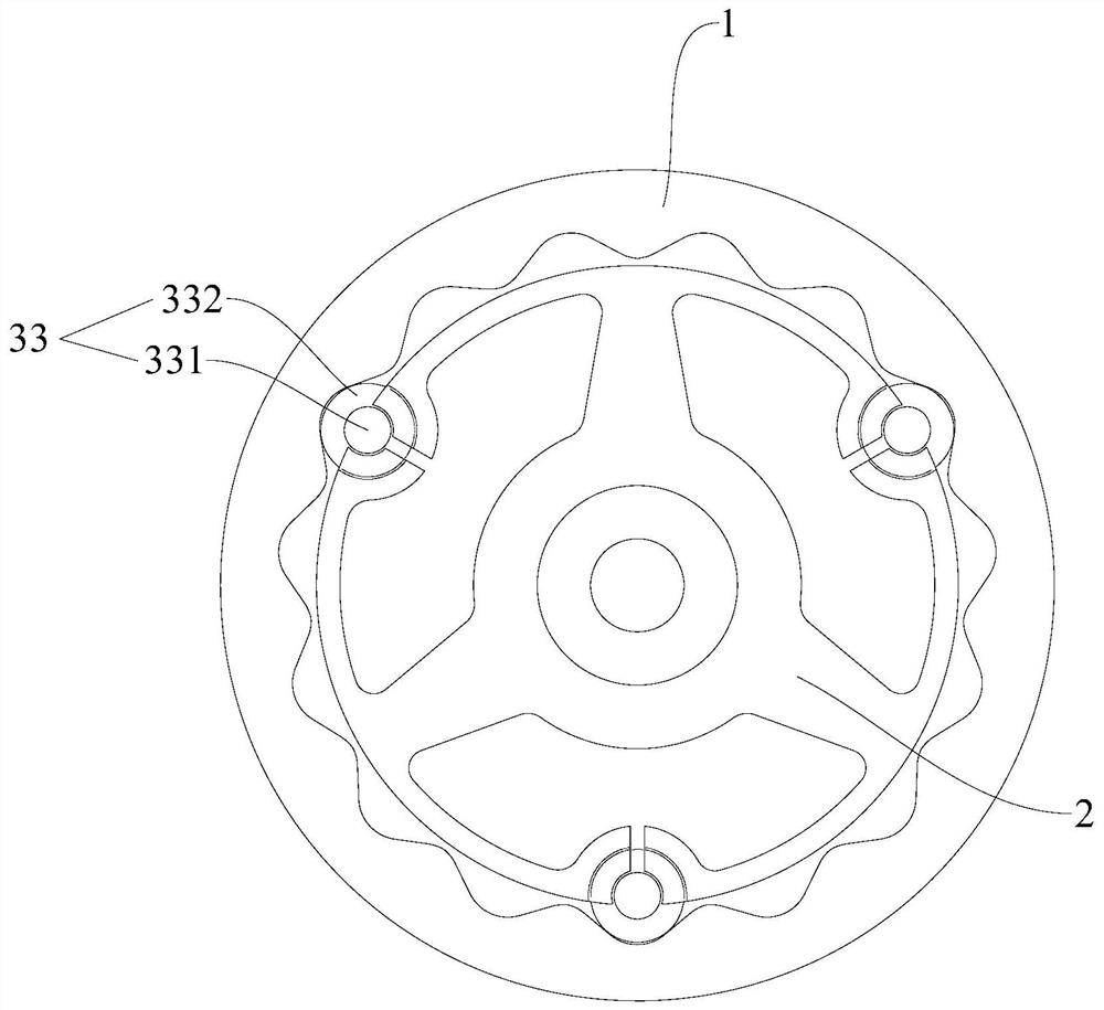
[0046] refer to Figure 7-8 , the difference between this embodiment and the first implementation is:
[0047] The wave track 31 is arranged on the outside of the second rotating member 2 , and the elastic supporting part is arranged on the inner side of the first rotating member 1 . Specifically, the wave track 31 is arranged outside the second rotating member 2, and the wave track 31 and the second rotating member 2 are integrally formed or the wave track 31 is combined with the second rotating member 2; the elastic support part is arranged on the first rotating member 1 The inner side, and the elastic support part is integrally formed with the first rotating part 1 or the elastic supporting part is combined with the first rotating part 1
[0048] Similarly, in this embodiment, the second rotating member 2 can also be used as the driving member, and the first rotating member 1 can be used as the driven member; or the first rotating member 1 can be used as the driving member...
PUM
 Abstract
Description
Claims
Application Information
 - Generate Ideas
- Intellectual Property
- Life Sciences
- Materials
- Tech Scout
- Unparalleled Data Quality
- Higher Quality Content
- 60% Fewer Hallucinations
Browse by: Latest US Patents, China's latest patents, Technical Efficacy Thesaurus, Application Domain, Technology Topic, Popular Technical Reports.
© 2025 PatSnap. All rights reserved.Legal|Privacy policy|Modern Slavery Act Transparency Statement|Sitemap|About US| Contact US: help@patsnap.com