
Convenient-to-adjust energy-saving lamp

A technology for LED energy-saving lamps and lamps, which is applied to cleaning methods and utensils, chemical instruments and methods, components of lighting devices, etc. Light effect, easy to adjust, easy to adjust effect

Inactive Publication Date: 2021-02-19
ANHUI AILAITE LIGHTING
View PDF1 Cites 2 Cited by
  • Summary
  • Abstract
  • Description
  • Claims
  • Application Information

AI Technical Summary

Problems solved by technology

The conveniently adjustable LED energy-saving lamps in the above-mentioned patents have the following deficiencies: it is inconvenient to adjust the light intensity during use, and the use is not flexible enough.

Method used


Image

  • Convenient-to-adjust energy-saving lamp
  • Convenient-to-adjust energy-saving lamp
  • Convenient-to-adjust energy-saving lamp

Examples


Embodiment 1

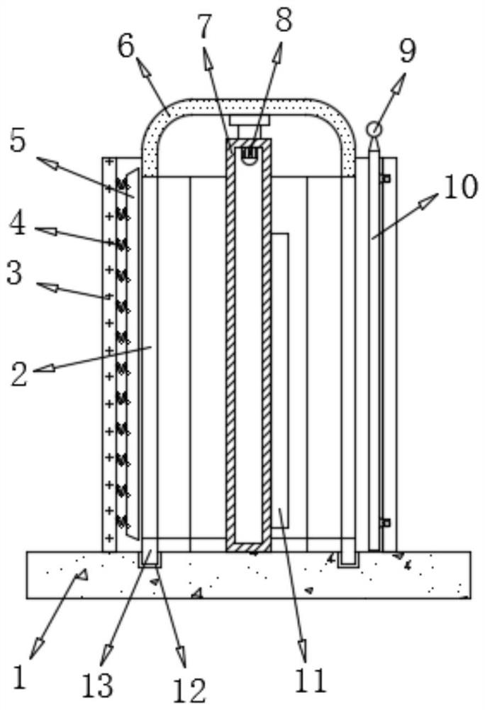
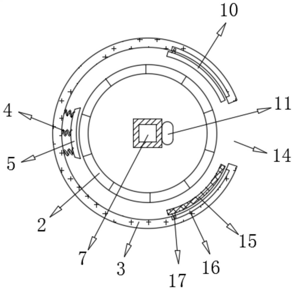
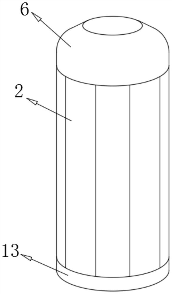
[0025] refer to Figure 1-3 , a conveniently adjustable energy-saving lamp, comprising a lamp holder 1, the top of the lamp holder 1 is connected with a mounting shell 7 by bolts, and the outer wall of one side of the mounting shell 7 is connected with an LED energy-saving lamp 11 by bolts, and the mounting shell 7 The inner wall of the top of the rotary motor 8 is connected with a rotating motor 8 through bolts, and the output shaft of the rotating motor 8 is connected with a rotating plate 6 through bolts, and the circumference of the bottom of the rotating plate 6 is connected with a dimmer cover 2 through bolts, and the dimmer cover 2 has the same size The arc-shaped pieces are spliced ​​into a cylindrical structure. The transparency of the arc-shaped pieces gradually changes from shallow to deep. The top of the lamp holder 1 is connected to the limit housing 3 by bolts, and the dimmer cover 2 is located inside the limit housing 3. , one side of the limiting housing 3 is p...

Embodiment 2

[0034] refer to Figure 4 , a conveniently adjustable energy-saving lamp. Compared with Embodiment 1, the outer wall of the installation shell 7 is connected with arc-shaped plates 18 by bolts along both sides of the LED energy-saving lamp 11, and the inner arc of the arc-shaped plate 18 Surfaces are coated with a reflective coating.

[0035] Working principle: When in use, the rotating plate 6 can be driven by the rotating motor 8 to rotate, thereby driving the dimmer cover 2 to rotate, and it is convenient to adjust the alignment of the arc-shaped pieces of different transparency of the dimmer cover 2 with the LED energy-saving lamp 11, and it is convenient to adjust the light Brightness, the limit housing 3 blocks the light of the LED energy-saving lamp 11, so that the light is emitted from the perforation 14. When the dimming cover 2 rotates, the support ring 13 supports the dimming cover 2. At the same time, the support ring 13 and the groove 12 Support and limit the rot...


PUM


Abstract

The invention discloses a convenient-to-adjust energy-saving lamp. The lamp comprises a lamp holder, a mounting shell is connected to the top of the lamp holder through bolts, an LED energy-saving lamp body is connected to the outer wall of one side of the mounting shell through bolts, a rotating motor is connected to the inner wall of the top of the mounting shell through bolts, an output shaft of the rotating motor is connected with a rotating plate through a bolt, the circumference of the bottom of the rotating plate is connected with a dimming cover through bolts, the dimming cover is of acylindrical structure formed by splicing arc-shaped pieces with the same size, the transparency of the arc-shaped pieces is gradually changed from shallow to deep, and the top of the lamp holder is connected with a limiting shell through bolts. When the LED lamp is used, the rotating plate can be driven by the rotating motor to rotate, so that the dimming cover is driven to rotate along with therotating plate, the arc-shaped pieces with different transparency of the dimming cover are conveniently adjusted to be aligned with the LED energy-saving lamp, the light brightness is conveniently adjusted, the limiting shell shields the light of the LED energy-saving lamp, and the light is emitted from a through hole.

Description

technical field [0001] The invention relates to the technical field of lamps, in particular to a conveniently adjustable energy-saving lamp. Background technique [0002] LED is a semiconductor light-emitting diode, which is a solid-state semiconductor device that can directly convert electricity into light. LED energy-saving lamps use high-brightness white light-emitting diodes as light sources, with high luminous efficiency, low power consumption, long life, easy control, maintenance-free, safe and environmentally friendly. [0003] After retrieval, the Chinese patent publication number is CN208951829U, which discloses a conveniently adjustable LED energy-saving lamp, including a lampshade. The top of the inner back of the lampshade is fixedly connected with a first positive and negative motor. The output shaft is fixedly connected with a first rotating rod, the top of the inside front of the lampshade is fixedly connected with a first bearing, and the end of the first ro...

Claims


Application Information

Patent Timeline
IPC IPC(8): F21S8/00F21V14/02F21V14/06F21V19/02F21V5/00F21V33/00B08B1/04F21Y115/10
CPCF21S8/00F21V14/02F21V14/06F21V19/02F21V5/00F21V33/00F21Y2115/10B08B1/32
Inventor 张胜利
Owner ANHUI AILAITE LIGHTING
Learn More