
Evaporative cooling unit control method and device and air conditioning equipment

An evaporative cooling and unit technology, applied in mechanical equipment, air-conditioning systems, lighting and heating equipment, etc., can solve problems such as coil dry spots, droplet splashing, and water drift, and achieve the effects of preventing dry spots and saving water consumption

Pending Publication Date: 2021-02-19
GREE ELECTRIC APPLIANCES INC
View PDF0 Cites 0 Cited by
  • Summary
  • Abstract
  • Description
  • Claims
  • Application Information

AI Technical Summary

Problems solved by technology

[0006] The embodiments of the present invention provide a control method and device for an evaporative cooling unit to solve the problem of dry spots formed on the coils of the evaporative cooling unit in the prior art and the problems of splashing and drifting of droplets caused by excessive spraying water

Method used


Image

  • Evaporative cooling unit control method and device and air conditioning equipment
  • Evaporative cooling unit control method and device and air conditioning equipment
  • Evaporative cooling unit control method and device and air conditioning equipment

Examples


Embodiment 1

[0063]The optional embodiments of the present invention will be described in detail below with reference to the accompanying drawings.

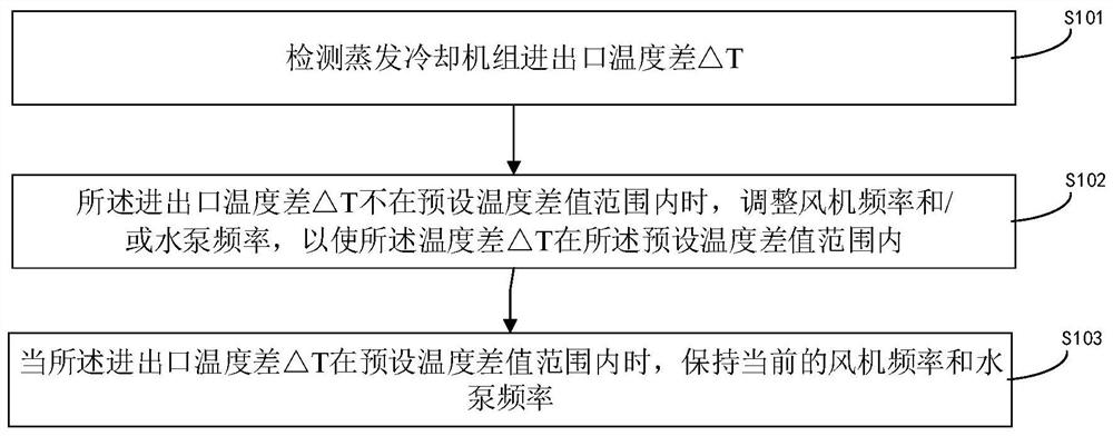
[0064]figure 1 It is a flowchart of an evaporative cooling unit control method according to an embodiment of the present invention, such asfigure 1 As shown, the method includes:

[0065]S101. Detect the temperature difference △T between the inlet and outlet of the evaporative cooling unit;

[0066]S102. When the inlet and outlet temperature difference ΔT is not within the preset temperature difference range, adjust the fan frequency and / or the water pump frequency so that the inlet and outlet temperature difference ΔT is within the preset temperature difference range ;

[0067]S103. When the inlet and outlet temperature difference ΔT is not within the preset temperature difference range, maintain the current fan frequency and water pump frequency.

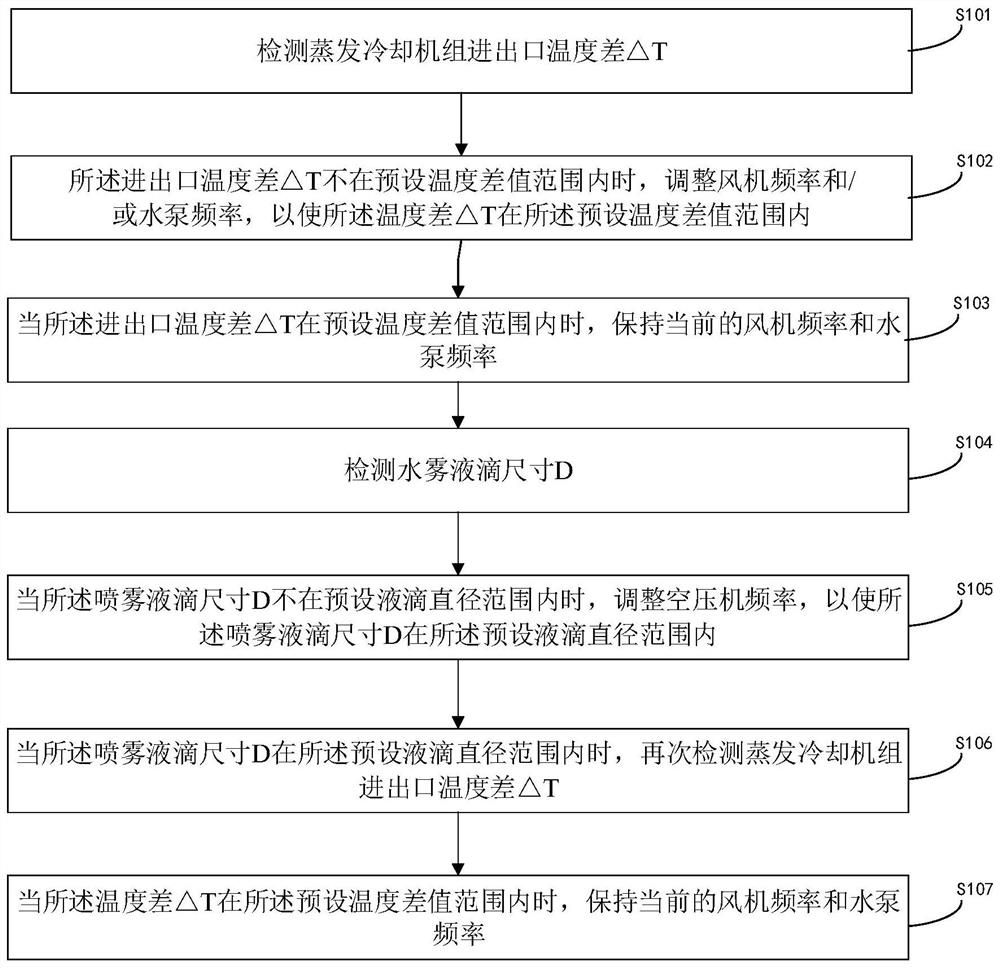
[0068]figure 2 It is a flowchart of another optional implementation manner of an evaporative cooling unit control ...

Embodiment 2

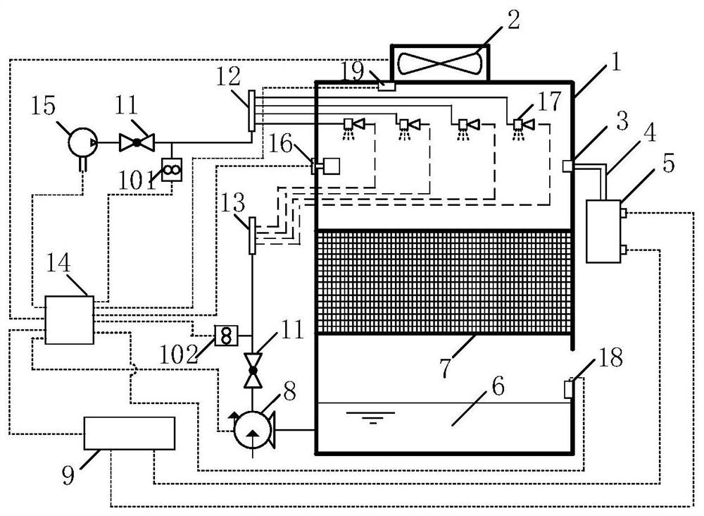
[0100]image 3 It is a structural diagram of a control device of an evaporative cooling unit provided by the present invention. As shown in the figure, the control device includes:

[0101]A signal receiving processor 14, and an air inlet temperature sensor 19 and an air outlet temperature sensor 18 respectively connected to the signal receiving processor;

[0102]The signal receiving processor 14 is also connected to the fan 2 and the water pump 8 of the evaporative cooling unit 1; an air inlet temperature sensor 19 arranged at the air inlet of the unit and an air outlet temperature sensor 18 arranged at the air outlet of the unit , Respectively used to detect the temperature at the air inlet and air outlet of the unit, and transmit the two temperatures to the signal receiving processor 14;

[0103]Such asimage 3 As shown, the inlet temperature sensor 19 is arranged next to the fan 2 and can detect the inlet temperature-it should be noted that the inlet temperature is the current ambient tem...


PUM


Abstract

The invention discloses an evaporative cooling unit control method and device and air conditioning equipment. The method comprises the steps that the inlet and outlet temperature difference T of an evaporative cooling unit is measured; when the inlet and outlet temperature difference T is not within a preset temperature difference value range, the frequency of a fan and / or the frequency of a waterpump are / is adjusted so that the inlet and outlet temperature difference T can be within the preset temperature difference value range; and when the inlet and outlet temperature difference T is within the preset temperature difference value range, the current fan frequency and the current water pump frequency are kept. By means of the method, a heat exchange coil can be prevented from forming dryspots, the water consumption in the refrigeration process is reduced, the situation that refrigeration cannot be implemented due to nozzle blockage is prevented, and the applicability of the evaporative cooling unit in different areas is improved.

Description

Technical field[0001]The present invention relates to the field of unit control, and in particular, to an evaporative cooling unit control method, apparatus, and air conditioning apparatus.Background technique[0002]Evaporative cooling air conditioning techniques are techniques for evaporating heat absorption using water. Under conditions without any other heat sources, the hot and humid exchange process between water and air is air to pass the heat to water, and the temperature of the air is lowered. Due to the evaporation of water, the moisture of air is not only increased, but also into the air vapor into some vaporization. As long as the air is not saturated, the effect of cooling can be obtained by directly (or by the filler layer). When the conditions are allowed, the cooling air can be used as a blow to reduce the room temperature, and the method of treating air is referred to as evaporative cooling air conditioning.[0003]Evaporative cooling units have increased significantly ...

Claims


Application Information

Patent Timeline
Patent Type & Authority Applications(China)
IPC IPC(8): F24F11/64F24F11/77F24F11/85F24F11/86F24F5/00F24F140/20
CPCF24F11/64F24F11/77F24F11/85F24F11/86F24F5/0035F24F2140/20Y02B30/70
Inventor 卓明胜李阳刘洋
Owner GREE ELECTRIC APPLIANCES INC
Learn More