
Fiber winding auxiliary tool for optical fiber macrobend loss test, and application method

An optical fiber macrobending and auxiliary tooling technology, which is used in optical instrument testing, measuring devices, testing optical fiber/optical waveguide equipment, etc., can solve the problem that the test results are easily affected by external factors, the efficiency of optical fiber macrobending loss testing is low, and the fiber winding Cumbersome work and other problems, to achieve the effect of convenient winding steps, protection from damage, and wide applicability

Pending Publication Date: 2021-02-19
TONGDING INTERCONNECTION INFORMATION CO LTD
View PDF0 Cites 2 Cited by
  • Summary
  • Abstract
  • Description
  • Claims
  • Application Information

AI Technical Summary

Problems solved by technology

[0004] The purpose of the present invention is to address the deficiencies of the prior art, to provide a fiber winding auxiliary tooling and application method for macrobending loss testing of optical fiber, so as to solve the problem of low working efficiency of macrobending loss testing of optical fiber, cumbersome fiber winding work, and easy test results. Affected by external factors, etc.

Method used


Image

  • Fiber winding auxiliary tool for optical fiber macrobend loss test, and application method
  • Fiber winding auxiliary tool for optical fiber macrobend loss test, and application method
  • Fiber winding auxiliary tool for optical fiber macrobend loss test, and application method

Examples


Embodiment Construction

[0034] In order to make the purpose, technical solutions and advantages of the embodiments of the present invention more clear, the technical solutions in the embodiments of the present invention will be clearly and completely described below in conjunction with the drawings in the embodiments of the present invention. Apparently, the described embodiments are some, not all, embodiments of the present invention. Based on the embodiments of the present invention, all other embodiments obtained by persons of ordinary skill in the art without making creative efforts belong to the protection scope of the present invention.

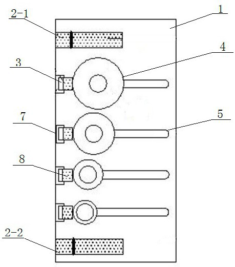
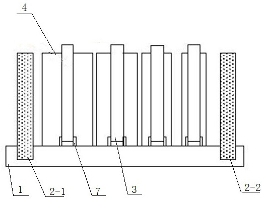
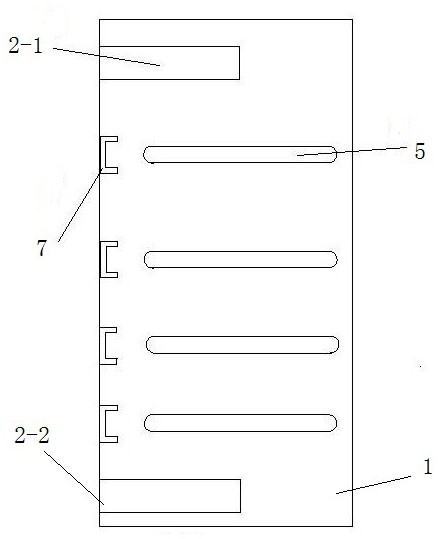
[0035] see Figure 1~6 , the embodiment of the present invention provides a fiber winding auxiliary tooling for optical fiber macrobend loss testing, including a chassis 1, a fiber guiding component 2, a fiber winding component and a fiber clamping part, an optical fiber guiding component 2, a fiber winding component and a fiber clamp The holding parts are al...


PUM

PropertyMeasurementUnit
thicknessaaaaaaaaaa

Abstract

The invention provides a fiber winding auxiliary tool for an optical fiber macrobend loss test. The fiber winding auxiliary tool comprises a chassis, an optical fiber guide assembly, a fiber winding assembly and optical fiber clamping components, wherein the fiber winding assembly comprises a plurality of fiber winding circular shafts with different diameters, the fiber winding circular shafts arevertically arranged on the chassis, each optical fiber clamping component corresponds to one fiber winding circular shaft, the optical fiber clamping component comprises a mounting shaft, a clampingpressing rod and a sponge strip, the sponge strip can be driven by the clamping pressing rod to rotate towards the fiber winding circular shaft and is in close contact with the fiber winding circularshaft, an optical fiber is introduced into the device through the optical fiber guiding assembly, optical fiber rings with different diameters are formed through surrounding of the optical fiber winding circular shafts with different diameters, and the optical fiber clamping components play a role in clamping the wound optical fiber rings. The invention further provides an application method of the device. According to the invention, the device can rapidly complete the winding work of various optical fibers, is small in size, can be fixed to various testing instruments for use, effectively improves the testing efficiency of optical fiber macrobend loss testing, and improves the stability of a testing result.

Description

technical field [0001] The invention belongs to the technical field of optical fiber performance detection, and in particular relates to an auxiliary fiber winding tool for optical fiber macrobending loss testing and an application method. Background technique [0002] The macrobending loss of optical fiber is an important test item for optical fiber performance, especially the bending insensitive single-mode fiber (G.657) series has stricter requirements for macrobending performance testing. When measuring the macrobending loss of a single-mode fiber, it is necessary to wind the fiber into a circle with a certain diameter according to the requirements, and measure the macrobending loss of the fiber by measuring the loss change between the bent and unbent state of the fiber. Most of the auxiliary tools currently used are single coiled cylinders or integrated auxiliary tools. A single coiled cylinder needs to be frequently replaced with multiple coiled cylinders with differen...

Claims


Application Information

Patent Timeline
Patent Type & Authority Applications(China)
IPC IPC(8): G01M11/00
CPCG01M11/30
Inventor 沈小平孙舒杨沈杰魏文涛白晓明
Owner TONGDING INTERCONNECTION INFORMATION CO LTD
Learn More